
螺旋齿轮与蜗轮:工业传动减速指南
Analyze the absolute mechanical boundaries of industrial power transmission. Evaluate rolling contact efficiency versus orthogonal sliding friction, thermal equilibrium constraints, static self-locking statics, and the strategic deployment of hybrid reduction architecture for heavy-duty rotary equipment.
Drive Reduction Architecture and Tribology
Specifying an industrial speed reducer for high-torque infrastructure requires a rigorous mathematical balance between mechanical efficiency, spatial limitations, and payload holding requirements. The foundational engineering debate analyzing a helical gear vs worm gear configuration is entirely dictated by tribology—the physics of friction, lubrication, and wear. These two transmission topologies do not merely differ in their physical external shape; they operate on fundamentally opposing kinematic principles. Helical transmissions transfer kinetic power through progressive rolling contact across parallel shafts, prioritizing ultra-high mechanical efficiency and cold operating temperatures. Conversely, worm drives redirect power across non-intersecting 90-degree orthogonal axes, prioritizing massive torque multiplication ratios and inherent resistance to gravitational back-driving.
Applying an incorrect gear architecture to a heavy industrial load invariably leads to catastrophic mechanical failure or severe electrical inefficiency. Utilizing a high-friction mechanism in an application requiring continuous, 24/7 high-speed operation will cause the gearbox lubricant to reach thermal breakdown, destroying the oil seals and the internal bronze components. Alternatively, deploying a highly efficient parallel reducer on an inclined mining conveyor without external mechanical braking systems invites massive regenerative back-driving, causing the aggregate payload to violently reverse direction when the electric motor loses power. Understanding the physical boundaries of these two mechanisms is the mandatory first step in powertrain procurement.
Performance and Kinematic Specification Matrix

Evaluating drivetrain efficiency requires mapping the mechanical friction losses against the required gear reduction ratio. The engineering table below benchmarks the absolute physical thresholds of standard multi-stage 斜齿轮 against heavy-duty industrial worm reduction units. These parameters are calculated assuming standard ISO 6336 gear life standards and continuous operational duty cycles (S1).
| Tribological Parameter | Parallel Helical Transmission | Right-Angle Worm Transmission |
|---|---|---|
| Spatial Shaft Alignment | Parallel Axes | Orthogonal (90-Degree) Non-Intersecting |
| Primary Mesh Friction | Rolling Contact (Negligible sliding) | High-Velocity Sliding Contact |
| Mechanical Efficiency | Very High (98.0% to 99.5% per stage) | Highly Variable (50% to 90% depending on ratio) |
| Single-Stage Ratio Ceiling | Geometrically limited to approx. 8:1 per stage | Massive capability (Up to 100:1 in a single pass) |
| Static Self-Locking Ability | None. Fully reversible and back-drivable. | Yes (Highly dependent on thread lead angle < 5°) |
| Thermal Heat Generation | Low. Ambient casing convection is sufficient. | Severe. Requires external ribbed cooling fins or fans. |
| Metallurgical Constraint | Forged Hardened Steel on Hardened Steel | Hardened Steel Worm on Sacrificial Bronze Wheel |
Kinematics of Helical Transmissions: Rolling Contact and EHL Oil Films
The absolute mechanical superiority of parallel-axis transmission lies in the specific nature of involute tooth engagement. Because the teeth are machined at an oblique angle across the cylindrical blank, the physical contact initiates at a localized point and progressively rolls diagonally across the face width. This continuous geometric progression ensures that the physical action between the mating steel surfaces is overwhelmingly rolling contact, with only a negligible percentage of specific sliding friction occurring near the absolute tooth root and tip limits.
This absence of abrasive sliding friction allows helical components to establish and maintain an intact Elastohydrodynamic Lubrication (EHL) oil film. The continuous rolling action acts as a localized pump, forcing extreme-pressure (EP) gear oil into a wedge shape that prevents the microscopic steel asperities from ever touching. As a direct thermodynamic result, these drives convert 98.5% of the input motor energy directly into output rotational torque. Very little kinetic energy is lost as radiant waste heat, meaning these gearboxes can operate at continuous high velocities (e.g., 3600 RPM motor inputs) without boiling the internal lubrication fluid or degrading the nitrile rotary seals.
However, this near-perfect internal efficiency introduces a specific mechanical vulnerability: parallel transmissions are completely and inherently back-drivable. If an electric motor loses phase power while hoisting a massive steel coil, the potential energy of the suspended weight will immediately overpower the minimal rolling friction of the gears. The gearbox will aggressively spin backward. Parallel architectures offer zero static holding torque, absolutely mandating the installation of external electromagnetic fail-safe brakes on the input shaft for any vertical lifting or inclined conveying applications.

Kinematics of Worm Mechanisms: Sliding Friction and Mixed Metallurgy

In stark contrast, a 蜗轮蜗杆 assembly achieves massive spatial reduction via an orthogonal, non-intersecting layout. A hardened steel threaded shaft (the worm screw) meshes perpendicularly against a concave-toothed wheel. Because the axes cross at 90 degrees, the physical interaction cannot roll. The hardened steel threads aggressively wipe and slide across the flanks of the driven wheel. This continuous sliding action operates in a state of boundary lubrication, physically stripping away standard oil films.
If both components were manufactured from carburized steel, the extreme localized frictional heat would cause immediate atomic galling, cold-welding the gears together under load. To mitigate this catastrophic seizure, manufacturers enforce a strict dissimilar metals policy. The input worm remains hardened steel, but the driven wheel is cast from a sacrificial, high-tin phosphor bronze (such as CuSn12). The bronze acts as a solid dry-lubricant bearing surface, yielding to the steel thread. Consequently, the bronze wheel is structurally designed as a consumable wear item that will eventually require factory replacement.
This sliding friction is a massive thermodynamic liability. Upwards of 30% to 50% of the electric motor’s input energy can be converted directly into waste heat in high-ratio boxes. Standard mineral oils oxidize and turn to sludge in this high-temperature environment, forcing engineers to specify premium Polyalkylene Glycol (PAG) synthetic fluids. The cast iron housings must be heavily ribbed, and often equipped with shaft-driven cooling fans, to increase the external surface area for thermal dissipation and prevent the lubricant from exceeding its critical boiling threshold.
The Physics of Static Self-Locking (Non-Backdrivable Systems)
Despite their severe thermodynamic inefficiencies and mandated bronze wear limits, engineers deliberately specify right-angle worm configurations for one unique mechanical phenomenon: static self-locking. While pure parallel gearboxes require external brakes to hold a suspended load, worm architectures can inherently prevent reverse motion through raw mechanical friction physics.
Whether the unit self-locks depends entirely on the mathematical relationship between the lead angle of the worm threads and the coefficient of static friction of the bronze/steel interface. When the lead angle of the screw is machined to be lower than the static friction angle (typically any angle below 4 to 5 degrees, corresponding to reduction ratios of 40:1, 60:1, or higher), the system physically binds when reverse force is applied to the output wheel.
In these specific high-ratio units, gravity attempting to push a heavy elevator carriage downward cannot generate enough rotational leverage to overcome the binding friction holding the worm thread against the wheel flank. The system locks statically. However, experienced powertrain designers understand that external vibrations or dynamic kinetic shocks can momentarily reduce the friction coefficient, causing the gear to “creep.” Therefore, while worm gears offer excellent inherent anti-backdrive safety for inclined conveyors, international safety standards still mandate secondary external braking circuits for human-rated passenger elevators.
The Hybrid Architecture: Specifying the Helical Worm Gearbox
Resolving Efficiency vs Ratio Bottlenecks
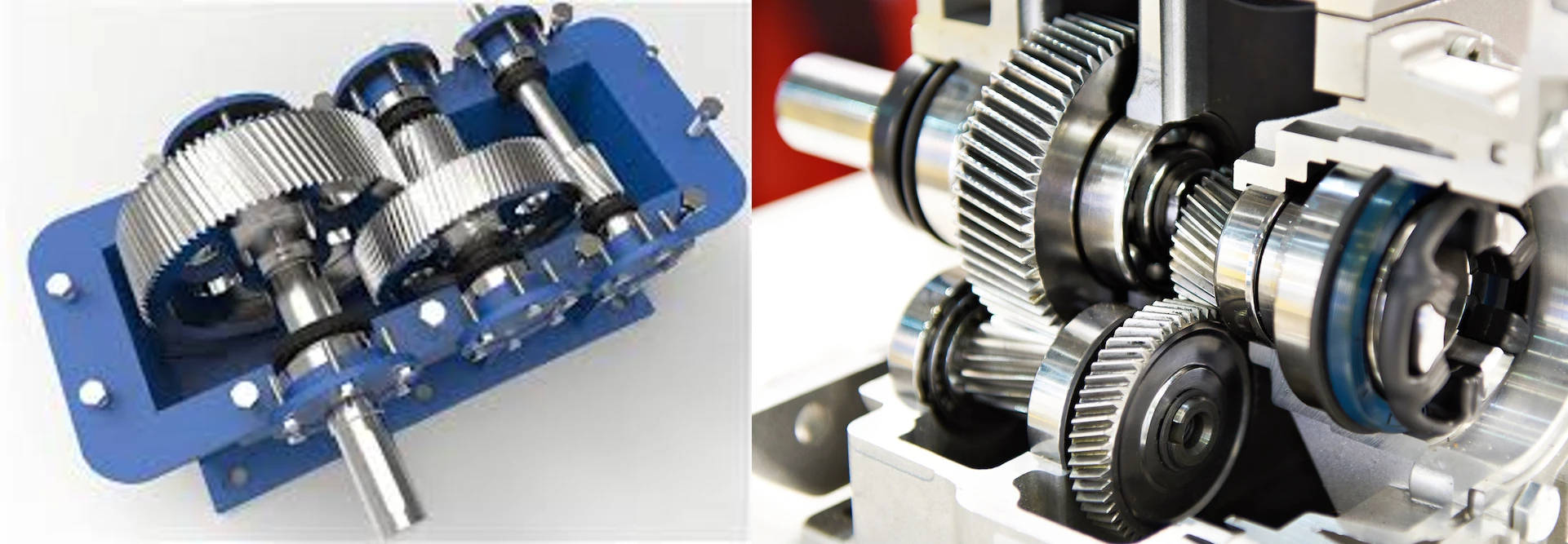
Industrial procurement teams often face a thermodynamic conflict: machinery requires a massive 120:1 reduction and a tight 90-degree spatial layout, but a standalone orthogonal stage would plummet to 45% efficiency, wasting enormous amounts of electricity. The engineering resolution is the 螺旋蜗轮 hybrid reducer. This sophisticated architecture mathematically splits the target ratio across two distinct physical stages.
Kinematic Sequence: The input shaft utilizes a high-efficiency parallel helical stage to perform the initial drop (e.g., 6:1 at 99% efficiency). This pre-reduced, torque-dense rotation feeds into the secondary orthogonal stage. Because the initial RPM is drastically lowered, the secondary worm only needs a modest ratio (20:1) to achieve 120:1 total. Operating the sliding mechanism at a lower ratio utilizes a steeper lead angle, which radically reduces sliding friction, elevating total system efficiency up to 80%.
High-Torque Double Helical Substitutions

When industrial applications exceed 10,000 Nm of continuous torque, the sliding friction of any worm-based architecture will instantly obliterate the bronze gear face. In heavy marine propulsion lines, metal shredders, and mining ball mills, engineers strictly specify massive multi-stage parallel drivetrains.
Engineering Substitution: To prevent the immense generated axial thrust from destroying the bearing bulkheads in these massive parallel units, designers bypass standard pinions and specify a 双螺旋齿轮. The opposing V-shaped tooth angles instantly cancel all internal thrust vectors, permitting extreme torque density with perfect rolling efficiency.
Korea Ever-Power: Precision Drive Manufacturing Authority

Extracting maximum operational lifespan from hybrid reduction systems requires uncompromising precision regarding involute profile accuracy and rigid bearing housing alignment. Operating as a premier 螺旋齿轮制造商 总部位于韩国, 韩国永动力蜗轮有限公司 engineers sophisticated parallel and orthogonal reduction mechanics for stringent B2B industrial buyers across Japan, Korea, and Southeast Asia.
- 毫不妥协的研磨精度: Leveraging our dedicated array of premium German HÖFLER profile grinding machinery, we consistently achieve strict DIN Class 3 to 6 accuracy to eliminate edge-loading and noise.
- 超大信封容量: Our ISO 9001 certified turning and hobbing infrastructure processes heavy-duty parallel drivetrain components reaching outer diameters (OD) up to 2500mm.
- 热力学稳定性: We execute precise atmospheric carburization cycles for parallel steel stages while deploying premium centrifugally cast bronze alloys for orthogonal stages, preventing premature sliding wear.
- Hybrid Engineering Support: Direct technical collaboration with procurement engineers to transition inefficient legacy right-angle boxes into high-efficiency hybrid arrangements.
工程常见问题 (FAQ)
Why can’t a parallel layout achieve the same high reduction ratio as a right-angle layout?
Parallel rolling engagement mathematically restricts the size differential between the driving pinion and the driven bull gear. Achieving a 60:1 ratio in a single parallel stage would require the driven gear to be geometrically 60 times larger in diameter than the pinion. A 5-inch input pinion would mandate a 25-foot diameter output gear, making the cast iron housing physically impossible to install in a standard factory. An orthogonal threaded screw architecture bypasses this geometric limit entirely, allowing up to 100 teeth to pass in a highly compact envelope.
How does synthetic lubrication affect hybrid drive performance?
Standard mineral EP oils break down rapidly under the intense shear forces and severe thermodynamic heat generated by orthogonal sliding friction. Furthermore, the active sulfur additives in EP gear oil aggressively corrode the bronze wheel. Upgrading a hybrid reducer to Polyalkylene Glycol (PAG) synthetic oil drastically reduces the coefficient of friction on the bronze while easily withstanding the high operational temperatures. This fluid switch can immediately elevate the mechanical efficiency of the sliding stage by 5% to 10%, directly reducing electricity consumption.
Is self-locking guaranteed on all right-angle orthogonal drives?
No. Self-locking is entirely dependent on the specific lead angle of the threaded steel cylinder. To guarantee static locking against a suspended payload, the lead angle must remain extremely shallow—typically under 5 degrees (usually found on ratios of 40:1 and higher). As you decrease the overall reduction ratio (e.g., dropping to 10:1), the manufacturer must increase the thread angle to move the teeth faster. Once the angle exceeds roughly 8 degrees, the static friction is overcome, and the heavy payload will violently back-drive the motor.
Can a spiral bevel gear replace the orthogonal sliding stage to eliminate heat?
Yes. For right-angle applications requiring massive torque and extremely high efficiency without thermal buildup, designers replace the sliding bronze wheel with a hardened spiral bevel gear stage. Spiral bevels operate on intersecting conical axes using pure rolling contact, yielding 97% to 98% efficiency. However, spiral bevel sets are significantly more expensive to manufacture, they physically cannot achieve massive 60:1 ratios in a single stage, and they completely lack the ability to self-lock, meaning an external friction brake is strictly mandatory.
What is the “run-in” period required for bronze-driven reduction units?
Unlike hardened parallel systems that arrive dimensionally perfect, a bronze orthogonal wheel requires a physical run-in period. During the initial 50 to 100 hours of operation under partial torque load, the hardened steel screw physically polishes and plastically deforms the softer bronze face, burnishing it to create a custom, highly optimized contact patch. Subjecting the gearbox to maximum rated torque prior to completing this run-in process causes premature bronze flaking, rapid wear, and severe overheating.
Upgrade Your Industrial Reduction Architecture
Do not allow extreme sliding friction to throttle your electrical efficiency or continuous throughput. Forward your drivetrain spatial schematics to Korea Ever-Power engineers to evaluate transitioning your legacy orthogonal drives into high-efficiency hybrid parallel configurations.
编辑:Cxm


























