
Why Failure Analysis Matters Before Ordering a Replacement
Installing a replacement spiralni zupčanik into a gearbox that failed without first diagnosing why it failed almost guarantees a repeat failure at the same or shorter service interval. The replacement gear is identical to the original — if the original failed at 18 months due to gear oil contamination with water, the replacement will also fail at 18 months. If the original failed due to insufficient face width (ε_β < 1) causing edge loading, a like-for-like replacement will fail identically. Correct failure analysis identifies whether the replacement gear needs a different specification, whether the lubrication must be changed, whether a seal must be repaired, or whether a machine alignment issue must be corrected before the new gear is installed.
Korea Ever-Power offers a failure analysis service alongside its reverse engineering capability: send the failed spiralno rezani zupčanik for visual and metallographic examination, and receive a failure mode report with root cause and specification recommendation before a replacement is ordered. Browse the Asortiman proizvoda sa spiralnim zupčanicima for replacement specifications.
Pitting — Surface Contact Fatigue, the Most Common Helical Gear Failure

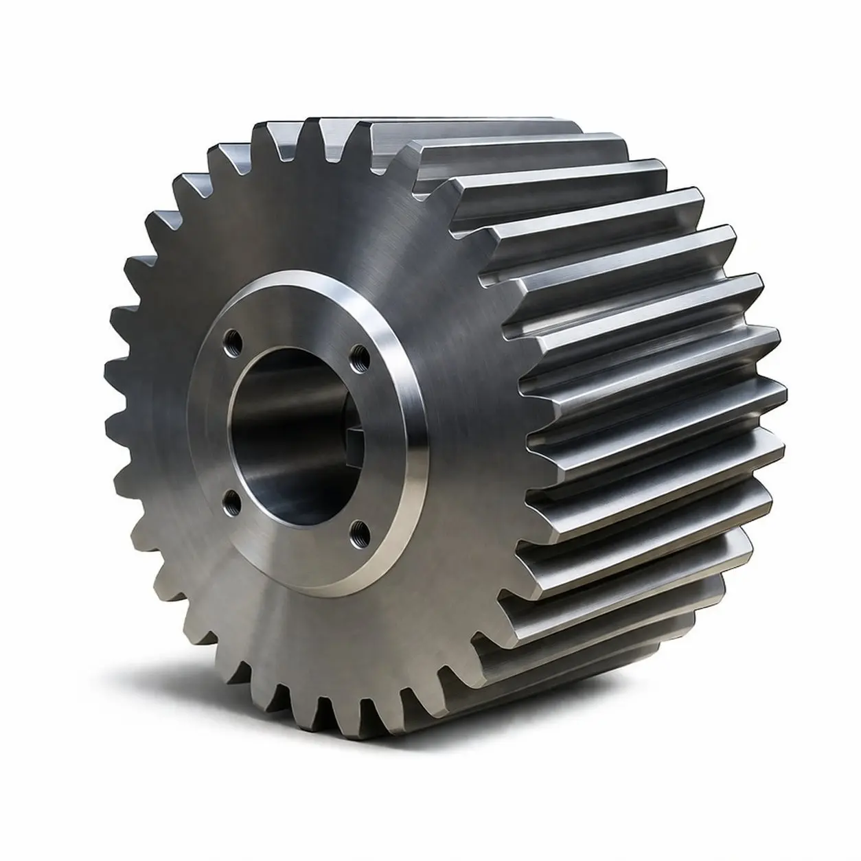
Tvrda bočna strana zuba cementirana spiralni zupčanik — the HRC 58–62 surface resists pitting when lubrication film is adequate. Pitting initiates at the pitch line where the EHL film is thinnest and sliding velocity is lowest, typically appearing as small hemispherical craters 0.1–1.0 mm diameter in early stages
Pitting: Visual Characteristics and Location
Pitting is surface fatigue — tiny cracks initiate at or just below the tooth flank surface and propagate under cyclic Hertzian contact stress until a small fragment detaches, leaving a roughly hemispherical crater (the “pit”). Pitting in a spiralni zupčanik has three distinctive location and appearance characteristics:
- Lokacija: Pitting initiates predominantly at or slightly below the pitch line — the position on the tooth flank where the EHL film is thinnest (lowest sliding velocity, minimum film thickness) and Hertzian contact stress is highest. In a single spiralni zupčanik, pits concentrate near the centre of the face width where the contact pattern is densest; at one face end if lead deviation (mis-alignment) is causing edge loading.
- Napredak: Initial pits (0.1–0.3 mm diameter) are hemispherical, with a smooth surface from the fatigue crack propagation. As pitting continues, adjacent pits coalesce into spalling — larger, irregular craters with rougher surfaces. Spalling accelerates rapidly once started because the rough spalled area disrupts the EHL film for neighbouring teeth.
- Distinguishing progressive vs destructive pitting: Progressive (acceptable) pitting produces pits that arrest after an initial running-in period — the rough surface redistributes load to a slightly wider contact zone, and the EHL film re-establishes. Destructive pitting continues to spread, with spalled areas growing. If pitting is still growing at the next inspection, it will not arrest without a root cause change.
Root Causes of Pitting in Helical Gears
| Root Cause | Mechanism | Diagnostic Evidence | Prevention |
|---|---|---|---|
| Lubricant film too thin (λ < 1.0) | Asperity contact exceeds material fatigue limit; cracks initiate at surface asperities | Pits concentrated at pitch line; oil sample shows high particle count but normal chemistry | Increase oil viscosity grade; check oil temperature; upgrade to synthetic PAO |
| Overload (F_t exceeds design value) | Contact stress σ_H exceeds σ_H lim; fatigue life consumed rapidly | Pitting across full face width; uniformly distributed; no edge concentration | Reduce transmitted load; increase gear size (module, face width); higher material grade |
| Edge loading from misalignment | Contact concentrated at one face end; local stress exceeds σ_H lim | Pitting concentrated at one face edge; opposite edge clean; lead deviation confirmed by analyser | Realign shaft or housing; specify lead crowning on replacement gear |
| Water or contaminant in oil | Water emulsifies oil; EHL film collapses; corrosion-fatigue accelerates crack propagation | Pits with rust staining; oil sample shows water content above 0.1%; white emulsion at oil fill | Repair seal allowing water ingress; replace oil; improve breather design |
Micropitting — The Fine-Scale Fatigue Preceding Full Pitting
Micropitting (also called grey staining, frosting, or corrosion fatigue in different industry standards) is a fine-scale surface damage mode that precedes full pitting in many spiralni zupčanik failures. Micropits are 10–100 µm diameter craters — too small to see individually with the naked eye, but producing a characteristic matte grey appearance on the tooth flank in the pitch line region. Under a ×20 optical microscope or SEM, the micropitting zone shows a dense array of tiny craters with angular edges, clearly distinct from the polished adjacent surface.
Micropitting forms when the specific film thickness ratio λ is in the range 0.4–1.0 — the mixed lubrication regime where occasional asperity contact occurs but full metal-metal contact has not yet developed. The micropits gradually merge and deepen, transitioning to macro-pitting after typically 10⁷–10⁸ contact cycles. Micropitting is particularly common in ground spiralni zupčanici during the first 200–500 hours of operation (running-in), after which the surface roughness reduces, the EHL film re-establishes, and the micropitting arrests. If micropitting continues beyond the running-in period, it indicates an inadequate lubricant for the operating conditions.
Scuffing (Scoring) — Catastrophic Film Breakdown
Scuffing: Visual Characteristics and Rapid Progression
Scuffing is an adhesive wear mechanism in spiralni zupčanici that occurs when the EHL film collapses completely and the mating tooth flanks weld at asperity contacts under the flash temperature generated by sliding. The welds tear as the tooth surfaces move relative to each other, producing characteristic linear furrows in the sliding direction across the tooth flank. Scuffing in a spiralni zupčanik appears as:
- Lokacija: Tooth tip and tooth root (where sliding velocity is highest and EHL film is thinnest). The pitch line itself is typically free of scuffing because sliding velocity is zero at this point. This distinctive location pattern distinguishes scuffing from pitting.
- Appearance: Irregular, rough surface with directional scoring marks in the sliding direction. The surface appears torn rather than smoothly pitted. Transfer of material from one gear to the other is often visible — bright metallic transfer patches on one tooth surface, corresponding dark abraded zones on the mating surface.
- Napredak: Scuffing is rapid and catastrophic. Once initiated, the rough scuffed surface destroys the EHL film for all subsequent tooth contacts, accelerating scuffing across the full tooth face within hours. There is no “tolerable” level of scuffing — any evidence of scoring requires immediate machine shutdown and gear replacement.
Root Causes and Prevention
Scuffing occurs when the tooth flank temperature exceeds a critical threshold at which the lubricant film can no longer form. Contributing factors: incorrect lubricant viscosity grade (too low for the operating speed), gear oil at high temperature (above 90°C sump), insufficient EP additive content for the specific gear tooth material pair, very high pitch-line velocity combined with inadequate oil flow to the mesh, and insufficient running-in (new gears at full load from cold start). Prevention: use the correctly specified oil grade with verified EP additive content (confirmed by FZG scuffing test stage ≥ 12); ensure adequate oil flow rate; follow the manufacturer’s running-in procedure for new gears; monitor sump temperature continuously in high-speed applications above 25 m/s.
Tooth Root Fracture — Bending Fatigue vs Impact Fracture
Tooth root geometry — fractures initiate at the highest bending stress point in the root fillet. Bending fatigue fracture shows a progressive beach-mark crack growth zone; impact fracture shows a clean brittle fracture surface without beach marks
Bending Fatigue Fracture — Progressive Crack Growth
Bending fatigue fracture in a spiralni zupčanik tooth initiates at the tensile side of the tooth root fillet (the side from which the tooth bends under load) and propagates progressively with each load cycle. The fracture surface has characteristic “beach marks” — concentric curved lines visible to the naked eye that indicate the position of the crack front at different stages of propagation. The crack growth zone is typically smooth and concave; the final fracture zone (where the remaining tooth cross-section was insufficient to carry the load and failed instantaneously) is rough and may show chevron marks or river lines indicating direction of final fracture propagation. Beach marks identify a fatigue fracture unambiguously — they are present in fatigue and absent in impact fractures.
Impact Fracture — Single-Event Overload
Impact fracture in a spiralni zupčanik tooth occurs when a single load event exceeds the tooth’s ultimate bending strength — typically entry shock (rolling mill bite, crusher bite), hydraulic hammer blow, or dropped load. The fracture surface is uniformly rough with no beach marks; chevron patterns on the fracture surface indicate the direction of crack propagation from the root fillet. Impact fracture is more common in induction-hardened gears (where the shallow hardened zone over a tough core can absorb most shock loads) than in carburized gears (where the case-core boundary creates a potential stress concentration under impact).
Abrasive Wear — Gear Surface Damage from Oil Contamination
Abrasive wear in spiralni zupčanici removes material evenly from the tooth flanks — both addendum and dedendum, not concentrated at the pitch line as with pitting — through the cutting and gouging action of hard particles suspended in the gear oil. The worn surfaces show directional scratches in the sliding direction, and the tooth profile gradually deviates from the original involute as material is continuously removed. The gear analyser report of a worn gear shows increasing profile deviation over successive inspections.
Za spiralni zupčanik drives in dusty environments: maintain ISO cleanliness class at or below ISO 16/14/11 (per ISO 4406) through regular oil filtration (full-flow filter with 10 µm absolute rating) and oil sampling. In mining and outdoor environments where seal integrity is difficult to maintain, increase the filtration and oil sampling frequency — monthly for critical drives, quarterly for standard drives.
Failure Mode Diagnostic Quick Reference
| What You See | Where on the Tooth | Failure Mode | Most Likely Root Cause |
|---|---|---|---|
| Hemispherical craters, 0.1–2 mm | Pitch line, face centre | Pitting (contact fatigue) | EHL film too thin; overload; insufficient σ_H lim |
| Hemispherical craters, face edge only | Pitch line, one face end | Edge-loading pitting | Shaft misalignment; excessive lead deviation; no lead crowning |
| Matte grey, fine-scale cratering | Pitch line extending toward tip and root | Micropitting (grey staining) | λ = 0.4–1.0; inadequate oil viscosity or additive package |
| Directional scoring, transferred metal | Tooth tip and root | Scuffing (adhesive wear) | Film collapse; oil overtemperature; insufficient EP additive |
| Fracture with beach marks | Root fillet, tensile side | Bending fatigue fracture | Overload; inadequate SF; small root fillet radius; material defect |
| Fracture without beach marks, rough | Root fillet, full cross-section | Impact fracture | Single overload event; shock impact above tooth breaking strength |
| Uniform directional scratching, full tooth height | Addendum and dedendum evenly | Abrasive wear | Hard particles in oil; failed filter; seal breach allowing contamination |
When the Replacement Helical Gear Needs a Different Specification
The failure mode of the original spiralni zupčanik directly determines whether the replacement requires a specification change. Three failure modes almost always require a specification upgrade rather than a like-for-like replacement:
Replacement spiralni zupčanik should specify lead crowning (5–15 µm) to bring contact back to face centre under shaft deflection. A like-for-like flat-lead replacement will edge-load and pit at the same rate as the original.
Replacement spiralni zupčanik should upgrade material tier: from soft flank (45# QT) to carburized grade (20CrMnTi), or from induction-hardened (42CrMo) to fully carburized. A like-for-like replacement has the same bending fatigue limit and will fracture at the same service interval.
Like-for-like spiralni zupčanik replacement combined with correct oil viscosity grade and running-in procedure typically prevents recurrence. Scuffing from oil overtemperature may also require an oil cooling system addition to the gearbox.
Korea Ever-Power — Failure Analysis and Replacement Specification
Korea Ever-Power’s failure analysis service accepts worn or failed spiralno rezani zupčanici for visual examination, gear analyser measurement, and metallographic section analysis (hardness traverse, case depth confirmation, grain flow assessment). The examination report identifies the failure mode, probable root cause, and whether the replacement gear requires a specification change (different material, accuracy class, lead crowning, or service factor). As a direct proizvođač spiralnih zupčanika, Korea Ever-Power can produce the replacement gear immediately after confirming the specification — without the additional delays of sending analysis results to a separate manufacturer.
Često postavljana pitanja
Light initial pitting at the pitch line of a spiralni zupčanik — typically small pits under 0.3 mm diameter covering less than 3% of the active tooth flank area — can sometimes be tolerated in soft tooth flank spiralni zupčanici where the pits redistribute contact stress and arrest naturally. Hard tooth flank gears (carburized HRC 58–62) should be replaced when pitting is observed, because spalling in a hard case propagates rapidly and accelerates. The decision rule: if pitting area is increasing on successive oil drain inspections (monthly oil particle count trending upward), the gear is in destructive pitting and should be replaced at the next scheduled shutdown.
Oil analysis is the first diagnostic step. If the oil shows: elevated particle count (ISO Class >19/17/14), water contamination, low viscosity from shear degradation, or depleted additive package — a lubrication root cause is strongly indicated. If the oil is clean and correctly specified, the failure is likely a material, geometry, or load issue. Metallographic section of the failed gear confirms: if the hardness traverse shows correct case depth and hardness profile, the material specification was met and the failure was mechanical overload or lubrication. If hardness is below specification, a heat treatment problem is implicated.
Edge-loading pitting occurs when the gear’s actual contact pattern is concentrated at one end of the face width rather than across the full face. The two primary causes are: (1) shaft or housing misalignment — if the gear shaft is not parallel to the mating shaft within the lead angle tolerance, the contact zone shifts to the nearside face edge; (2) insufficient lead crowning — a flat tooth lead with no crowning has no tolerance for deflection-induced misalignment under load, and any deflection shifts the contact zone to an edge. The fix for a replacement spiralni zupčanik is to specify lead crowning of 5–15 µm (depending on face width and expected shaft deflection) to bring the contact back to centre under operating load.
Case crushing is a sub-surface fatigue failure that occurs below the carburized case of a hard tooth flank spiralni zupčanik. It initiates at the case-core boundary — where the hardness transitions from HRC 58–62 (case) to HRC 30–38 (core) — and propagates as a crack parallel to the tooth surface. The result is a large fragment that detaches across the entire case depth rather than the small surface pit of normal pitting. Case crushing is indicated by large (2–10 mm) fragments with a relatively flat fracture surface, appearing suddenly without the progressive small-pit precursor of normal pitting. Root cause: case depth too shallow for the transmitted load (the subsurface shear stress peak penetrates below the case-core boundary); or overload event exceeding the case-core boundary strength. Prevention: specify adequate minimum case depth per ISO 6336-5 for the transmitted contact stress level.
Submit a Failed Helical Gear for Analysis
Send your failed gear for visual examination, gear analyser measurement, and metallographic section report. Korea Ever-Power identifies the failure mode and root cause — and produces the correctly specified replacement without additional lead time delays.
Visual examination · Gear analyser · Metallographic section · Root cause report · Replacement specification
Urednik: Cxm


























