
Four Sources of Power Loss in a Helical Gear Drive
The total efficiency η_total of a 螺旋齿轮 drive is the product of the efficiencies of all individual loss sources. For a single-stage enclosed 螺旋齿轮箱, four independent mechanisms consume power from the 螺旋齿轮 drive:
Sliding friction between tooth flanks during approach and recess phases of mesh engagement. This is the dominant efficiency loss in a 螺旋齿轮 drive, accounting for 50–70% of total gearbox power loss. Mesh loss scales directly with transmitted load (it disappears at zero load). Typical contribution: 0.5–1.5% of transmitted power per mesh stage.
Rolling element bearing friction in the shaft support bearings. For deep-groove ball bearings: η_bearing ≈ 99.5% per bearing at moderate speed and load. For cylindrical roller bearings at high speed and load: η_bearing ≈ 98.5–99%. Two bearing pairs per shaft add 0.5–1.5% total bearing loss for a typical single-stage 螺旋齿轮 unit.
Oil viscous churning as the 螺旋齿轮 rotates through the oil bath, and aerodynamic windage at high speed. Churning loss ∝ n² × ρ_oil × d_gear³ — it becomes dominant at high pitch-line velocities (>15 m/s) and with overfilled oil sumps. Churning accounts for 0.5–3% of power loss in splash-lubricated gearboxes at high speed.
Lip seal drag on the input and output shafts. Each lip seal dissipates approximately 10–30 W at typical shaft diameters and speeds — negligible for high-power drives (>50 kW) but relevant for small 螺旋齿轮 units below 5 kW where seal loss can represent 1–3% of rated power.
Helical Gear Mesh Efficiency — The Sliding Loss Formula
The gear mesh efficiency of a 螺旋齿轮 pair is primarily determined by the coefficient of sliding friction f at the tooth contact zone and the gear geometry. The Benedict-Kelley and Niemann sliding loss approaches give mesh power loss P_VZP as:
η_mesh = 1 − P_VZP / P_transmitted
P_VZP = f × F_t × v_s_mean × ε_α
where: f = mean sliding friction coefficient (see table below)
F_t = tangential force at pitch circle [N]
v_s_mean = mean sliding velocity at tooth contact ≈ π × (1/z₁ + 1/z₂) × F_t/(b × mn) × [mm/s]
ε_α = transverse contact ratio
For practical 螺旋齿轮 design, the simplified Niemann formula gives mesh efficiency as a function of gear ratio u and friction coefficient f:
η_mesh ≈ 1 − f × π × (1/z₁ + 1/z₂) / cos(α_t) × (1 + 0.25 × ε_β²)⁰·⁵
Simplified to: η_mesh ≈ 1 − f × π × (u + 1) / (u × z₁ × cos α_t)
| Operating Condition | Friction Coefficient f | Typical η_mesh per Stage | 评论 |
|---|---|---|---|
| Ground gear, PAO synthetic oil, fully EHL film (λ ≥ 2) | 0.025–0.040 | 99.0–99.5% | Best achievable: precision 螺旋齿轮, DIN Class 4–5, ISO VG 100–220 PAO at operating temperature |
| Ground gear, mineral oil, EHL film (λ = 1.5–2.5) | 0.040–0.060 | 98.5–99.2% | Standard industrial precision 螺旋齿轮 with ISO VG 220 mineral oil |
| Hobbed gear, mineral oil, partial EHL (λ = 1.0–1.5) | 0.060–0.090 | 97.5–98.5% | DIN Class 7–8 hobbed gear; rougher tooth surface increases boundary friction |
| QT soft-flank gear, high viscosity oil, marginal film | 0.090–0.120 | 96.5–97.5% | Soft-flank gear, HB 280, ISO VG 320 gear oil — higher friction from asperity contact |
Total Gearbox Efficiency — Combining All Loss Sources
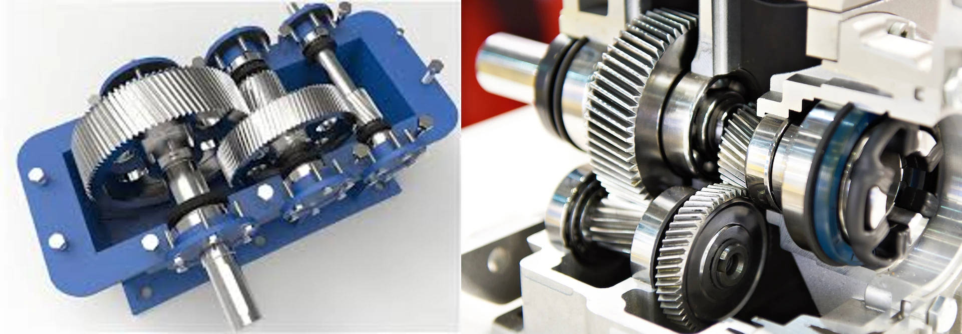
Helical gearbox — the four power loss sources are located at the tooth mesh (dominant at high load), shaft bearings (proportional to bearing load), oil sump (churning loss increases with speed), and shaft seals (minor except at very small power levels). The sum determines the total efficiency and heat load to be dissipated
For a typical single-stage enclosed 螺旋齿轮 gearbox unit with two deep-groove ball bearings per shaft and two lip seals:
η_total = η_mesh × η_bearings × η_churning × η_seals
Example: 75 kW, 1500 RPM input, M5, ground gear, mineral oil, normal speed
η_mesh = 98.8% (f = 0.055, u = 3.0, z₁ = 24)
η_bearings = 99.0% (4 deep-groove ball bearings, moderate load)
η_churning = 99.5% (v = 5 m/s pitch-line velocity; moderate churning)
η_seals = 99.8% (2 × 30 W seal loss on 75 kW)
η_total = 0.988 × 0.990 × 0.995 × 0.998 = 97.2%
P_loss = 75 kW × (1 − 0.972) = 2.1 kW heat generated in gearbox housing
Heat Generation and Oil Temperature Rise Calculation
The 2.1 kW heat load in the above 螺旋齿轮 example must be continuously dissipated through the gearbox housing surface to the ambient air. The equilibrium oil temperature rise ΔT above ambient is:
ΔT_oil = P_loss / (k_h × A_housing)
where: k_h = natural convection heat transfer coefficient of housing surface
= 15–25 W/(m²·K) for standard cast iron or aluminium housing without fan
= 25–40 W/(m²·K) for housing with external cooling fins
= 40–80 W/(m²·K) for housing with integral fan
A_housing = outer surface area of gearbox housing [m²]
For the 75 kW example gearbox with housing outer area A = 0.8 m² and k_h = 20 W/(m²·K):
ΔT_oil = 2100 W / (20 × 0.8) = 131°C above ambient
When Is an Oil Cooler Required? — Thermal Rating Decision
| Cooling Method | k_h (W/m²·K) | Maximum Heat Load P_loss per m² Housing | When Sufficient |
|---|---|---|---|
| Natural convection, unpainted housing | 12–18 | 600–900 W/m² (for ΔT = 50°C limit) | Small 螺旋齿轮箱 below ~30 kW at standard industrial speeds |
| Cooling fins on housing exterior | 18–30 | 900–1500 W/m² | Medium gearboxes 30–100 kW where housing area can be increased |
| External shaft-driven cooling fan | 35–60 | 1750–3000 W/m² | Compact gearboxes 50–200 kW where housing enlargement is impractical |
| External oil-to-air or oil-to-water cooler | N/A (cooler rated by kW capacity) | Unlimited (sized to P_loss) | Any 螺旋齿轮箱 above 200 kW, or any gearbox where ambient temperature > 40°C |
Efficiency Comparison — Helical Gear vs Other Drive Types

Korea Ever-Power efficiency test bench — input and output torque and speed are measured simultaneously; power loss = P_in − P_out; results confirm the mesh efficiency prediction from the friction coefficient model for the specified 螺旋齿轮 material, oil grade, and pitch-line velocity
| Drive Type | Efficiency per Stage | Ratio Range (single stage) | 笔记 |
|---|---|---|---|
| 螺旋齿轮 (ground, synthetic oil) | 98.5–99.5% | 1:1 to 8:1 | Best efficiency; requires parallel shafts |
| Helical gear (hobbed, mineral oil) | 97.5–98.5% | 1:1 to 8:1 | Standard industrial quality |
| 锥齿轮(直齿轮或螺旋齿轮) | 97–99% | 1:1 to 6:1 | 90° shaft angle; spiral bevel approaches helical efficiency |
| Planetary helical (3 planets) | 97–99% (total stage) | 3:1 to 10:1 | Multiple meshes in parallel; compact but 3 meshes compound the loss |
| Worm gear (lead angle 20–25°) | 82–90% | 5:1 to 80:1 | High ratio in single stage but 3–5× more heat than helical at same power |
| Worm gear (lead angle 5–10°) | 60–75% | 20:1 to 100:1 | Self-locking risk; high heat generation; thermal rating governs |
Korea Ever-Power — Thermal Rating Documentation with Gearbox Orders
For every custom enclosed 螺旋齿轮 drive assembly order, Korea Ever-Power provides a thermal rating calculation confirming the equilibrium oil temperature at the specified operating conditions (power, speed, ambient temperature, duty cycle). The calculation uses the actual mesh friction coefficient estimated from the specified oil grade and gear accuracy class, the housing surface area from the dimensional layout, and the required cooling method to maintain oil temperature within the specified range. As a direct 螺旋齿轮制造商, Korea Ever-Power’s thermal rating is included in the order documentation — not as an afterthought but as a standard verification step before the gearbox is assembled. Browse the 螺旋齿轮产品系列 for all standard and custom drive applications.
常见问题解答
PAO (polyalphaolefin) synthetic oil has a viscosity index of 140–160 versus 90–110 for mineral oil. This means PAO maintains adequate viscosity at high operating temperature while having lower viscosity at room temperature — both effects are beneficial. Lower traction coefficient (the ratio of tangential force to contact force in the EHL contact zone) is the primary mechanism: PAO contacts have approximately 20–30% lower traction coefficient than equivalent mineral oil contacts at the same viscosity. For a 螺旋齿轮 drive running on mineral oil at η_mesh = 98.8%, switching to PAO improves to approximately 99.1–99.2% — a heat load reduction of 20–25% at the same transmitted power.
In theory, increasing β slightly reduces η_mesh for a standard single-helix 螺旋齿轮 because the axial sliding velocity component increases with tan β. In practice, this effect is small (less than 0.1% difference between β = 15° and β = 25°) and is outweighed by the indirect benefits: higher β gives higher contact ratio ε_β, which reduces the dynamic load factor K_V, which allows a smaller (lighter, lower churning loss) gear for the same transmitted torque. For the standard industrial β = 15–25° range, efficiency differences are below measurement uncertainty for most gearboxes. The choice of helix angle is correctly made on noise, thrust bearing capacity, and contact ratio grounds — not efficiency.
The mechanical power rating of a 螺旋齿轮箱 is the maximum power at which the gear teeth do not fail in contact fatigue or bending fatigue within the design service life. The thermal horsepower rating (thermal power rating) is the maximum power at which the gearbox housing can dissipate enough heat to maintain the oil temperature below the maximum allowable (typically 80–90°C for mineral oil, 100–110°C for synthetic). For large, slow-running 螺旋齿轮 gearboxes with small housing surface area, the thermal rating is often lower than the mechanical rating — the mechanical teeth are strong enough to transmit the power, but the housing cannot dissipate the resulting heat fast enough. In this case, the usable power rating is the thermal rating, not the mechanical rating.
螺旋齿轮 mesh efficiency improves slightly at part load because the sliding friction loss P_VZP is proportional to the transmitted tangential force F_t — at 50% load, mesh loss is 50% of the full-load value. However, churning and seal losses are independent of load. Therefore, the total 螺旋齿轮箱 efficiency at 50% load is slightly lower than at full load — the fixed churning and seal losses represent a larger fraction of the (smaller) transmitted power. For 螺旋齿轮 drives operating predominantly at part load (below 60% of rated), this effect justifies consideration of a smaller gearbox with a higher safety factor, rather than oversizing to a large gearbox that operates mostly at 20–30% load with disproportionately high fixed losses.
Thermal Rating Calculation for Your Helical Gear Drive
Provide your power, speed, gear ratio, ambient temperature, and duty cycle. Korea Ever-Power calculates η_total, P_loss, and equilibrium oil temperature — confirming whether natural convection, forced air cooling, or an oil cooler is required before the gearbox is built.
η_mesh formula · P_loss calculation · Oil temp rise · Cooling method selection · Included with every gearbox order
编辑:Cxm


























