Product Description
Product Description
| Material | Aluminium Alloy,Carbon Steel,Stainless steel,Copper,Brass,Nylon,Plastic(Customized Material) |
| Producing Equipment | 3 Axis,4 Axis,5 Axis CNC Machines,Automatic Lathe Machines,Stamping Machines,CNC Milling machines,CNC Turning Machines,Turning Milling Compound Machines,Grinding Machines,Rolling Machines,Laser Machines. |
| Surface Treatment | Anodizing,Polishing,Electroplating,Heat Treatment,Spray Paint,Sand Blasting. |
| Testing Equipment | Salt Spray Test, Hardness Tester, Coating Thickness Tester, Two Dimensions Measuring Instrument. |
| Quality Testing | 100% Quality Inspection Before Shipment. |
| Lead Time | Generally, The Delivery Date Is 7-15 Days,Delivery Time of Bulk Order Is More Than 15 days. |
| Tolerance and Roughness | Size Tolerance:+/-0.005 – 0.01mm,Roughness: Ra0.2 – Ra3.2 (Custom Size Requirements) |
| Cargo Shipment | Express(DHL,Fedex,UPS, TNT ),Air shipment+Local Express Delivery,Ocean Shipment. |
| Main Markets | America, Europe, Australia, Asia. |
| Payment Type | T/T, L/C, Paypal,Western Union,Others. |
Packaging & Shipping
Company Profile
HangZhou CHINAMFG Technology Co., Ltd. Was established in city known as the “world factory”-HangZhou. We are factory and have many kinds of machine, such as 5-axis CNC machines, lath machines, turning milling compound machines. After 10 years of R&D, production and sales, we have 80% market share in the field of 3D printer parts in China and we are specializing in CNC machinig for 10 years. We are committed to creating a work and production environment that is above the industry average. We adopt scientific production management methods to improve production efficiency and reduce production costs. Please believe and choose us! We adhere to the management principles of “Quality First, Customer first and Credit-based” since the establishment of the company and always do our best to satisfy potential needs of our customers. Our company is sincerely willing to cooperate with enterprises from all over the world in order to realize a CHINAMFG situation since the trend of economic globalization has developed with anirresistible force.
Our Advantages
FAQ
| Condition: | New |
|---|---|
| Certification: | CE, RoHS, ISO9001 |
| Standard: | GB |
| Customized: | Customized |
| Material: | Stainless Steel |
| Application: | Metal Processing Machinery Parts |
| Samples: |
US$ 2/Piece
1 Piece(Min.Order) | |
|---|
| Customization: |
Available
| Customized Request |
|---|

What lubrication is required for helical gears?
Proper lubrication is essential for the optimal performance and longevity of helical gears. The lubrication requirements for helical gears depend on factors such as the operating conditions, gear materials, and manufacturer recommendations. Here’s a detailed explanation of the lubrication considerations for helical gears:
- Lubricant Selection: The choice of lubricant for helical gears should be based on factors such as operating temperature, load, speed, and environmental conditions. Commonly used lubricants for helical gears include mineral oils, synthetic oils, and greases. Consult the gear manufacturer’s specifications or industry standards to determine the appropriate lubricant viscosity and type for your specific application.
- Viscosity: The lubricant viscosity is an important parameter that influences the lubricating film thickness and the ability to separate the gear surfaces. The viscosity should be selected based on the operating conditions, taking into account factors such as temperature, speed, and load. Higher viscosity lubricants are typically used for heavy-duty applications or high-temperature environments, while lower viscosity lubricants may be suitable for lighter loads or lower speeds.
- Extreme Pressure (EP) Additives: Helical gears, especially those operating under high loads or with high sliding velocities, may benefit from lubricants containing extreme pressure (EP) additives. EP additives help to reduce friction and wear by forming a protective film on the gear surfaces, preventing metal-to-metal contact and minimizing the risk of scuffing or scoring. EP additives are particularly important for helical gears in industrial machinery, automotive transmissions, and gearboxes.
- Lubrication Method: The lubrication method for helical gears can vary depending on the gear design and application. Common methods include splash lubrication, oil bath lubrication, forced circulation systems, and oil mist lubrication. The lubrication method should ensure that an adequate amount of lubricant reaches the gear mesh to provide proper lubrication, cooling, and debris removal during operation.
- Frequency of Lubrication: Regular lubrication maintenance is crucial for helical gears. The lubrication intervals should be determined based on factors such as the gear operating conditions, lubricant type, and gear manufacturer recommendations. Periodic inspections should be conducted to monitor the lubricant condition, check for contamination or degradation, and replenish or replace the lubricant as needed.
- Proper Lubricant Application: When applying the lubricant to helical gears, ensure that the gear teeth and bearings are adequately coated. Pay attention to reaching areas of high friction and contact, such as the gear mesh and tooth roots. Follow the gear manufacturer’s recommendations or guidelines for the proper lubrication technique, which may involve methods such as oil bath immersion, drip lubrication, or centralized lubrication systems.
- Contamination Control: Contamination can significantly affect the performance and lifespan of helical gears. Take measures to prevent the ingress of contaminants such as dirt, dust, moisture, and metal particles into the gear system. Use proper sealing arrangements, filtration systems, and regular maintenance practices to maintain a clean and contamination-free lubrication environment.
It is important to note that the lubrication requirements may vary depending on specific gear designs, materials, and operating conditions. Always refer to the gear manufacturer’s recommendations, industry standards, and consult with lubrication experts or engineers to determine the most suitable lubrication approach for your helical gear application.

How do you retrofit an existing mechanical system with helical gears?
Retrofitting an existing mechanical system with helical gears involves replacing the current gear system with helical gears to improve performance, efficiency, or address specific requirements. The process requires careful planning, analysis, and implementation to ensure a successful retrofit. Here is a detailed explanation of how to retrofit an existing mechanical system with helical gears:
- Assess the Existing System: Begin by thoroughly assessing the existing mechanical system. Understand its design, operating conditions, gear specifications, and performance limitations. Identify the reasons for retrofitting, such as the need for increased load capacity, improved efficiency, noise reduction, or other specific requirements.
- Define Retrofit Objectives: Clearly define the objectives of the retrofit. Determine the specific improvements or modifications desired from the retrofit. This could include increasing torque capacity, reducing backlash, improving gear meshing characteristics, or optimizing gear ratios. Having well-defined objectives will guide the retrofitting process.
- Perform Gear Design and Analysis: Based on the defined objectives, conduct gear design and analysis to determine the appropriate helical gear configuration. Consider factors such as gear size, tooth profile, helix angle, module or diametral pitch, and gear material. Use engineering calculations, software simulations, or consult with gear design experts to ensure the selected helical gears meet the retrofit objectives and are compatible with the existing system.
- Modify Gear Housing and Mounting: In some cases, retrofitting with helical gears may require modifications to the gear housing or mounting arrangements. Ensure that the gear housing can accommodate the helical gears and provide proper alignment and support. Modify or adapt the housing as necessary to ensure a precise fit and alignment of the new gear system.
- Manufacture or Source Helical Gears: Once the gear design is finalized, manufacture or source the helical gears according to the specifications determined during the design phase. Work with experienced gear manufacturers or suppliers who can provide high-quality helical gears that meet the required specifications and performance criteria.
- Installation and Alignment: Remove the existing gears and install the helical gears in the mechanical system. Ensure proper alignment of the gears to maintain smooth operation and minimize wear. Follow recommended installation procedures and torque specifications provided by the gear manufacturer. Consider using alignment tools, such as dial indicators or laser alignment systems, to achieve precise gear alignment.
- Test and Fine-tune: After installation, conduct thorough testing of the retrofit system. Monitor performance, check for any abnormal vibrations, noise, or operating issues. Fine-tune the system as needed, making adjustments to gear meshing, lubrication, or other parameters to optimize performance and ensure the retrofit objectives are met.
- Monitor and Maintain: Once the retrofit is complete, establish a regular monitoring and maintenance schedule. Periodically inspect the helical gears for wear, perform lubrication checks, and address any maintenance requirements. Regular monitoring and maintenance will help ensure the longevity and optimal performance of the retrofit system.
Retrofitting an existing mechanical system with helical gears can significantly enhance its performance, efficiency, and reliability. However, it is essential to carefully plan and execute the retrofitting process to achieve the desired outcomes. Consulting with gear design experts and experienced professionals can provide valuable guidance and expertise throughout the retrofitting process.

Are there different types of helical gears available?
Yes, there are different types of helical gears available to meet specific application requirements. Here’s a detailed explanation of some common types of helical gears:
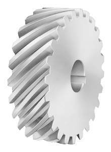
- Parallel Helical Gears: Parallel helical gears are the most commonly used type of helical gears. In this configuration, two helical gears with parallel axes are meshed together. They transmit power and motion between parallel shafts. Parallel helical gears provide smooth operation, high load-carrying capacity, and efficient power transmission.
- Double Helical Gears (Herringbone Gears): Double helical gears, also known as herringbone gears, have two sets of helical teeth that are placed in a V-shaped configuration. The V-shaped teeth face each other, with a groove or gap in the middle. This design cancels out the axial thrust that is generated by the helical gear’s inclined teeth. Double helical gears are often used in applications that require high torque transmission and axial load balancing, such as heavy machinery and marine propulsion systems.
- Crossed Helical Gears (Screw Gears): Crossed helical gears, also referred to as screw gears, involve the meshing of two helical gears with non-parallel and non-intersecting axes. The gears are oriented at an angle to each other, typically 90 degrees. Crossed helical gears are used in applications where shafts intersect or when a compact and non-parallel gear arrangement is required. They are commonly found in hand drills, speedometers, and some mechanical watches.
- Skew Gears: Skew gears are a type of helical gear in which the gear teeth are cut at an angle to the gear axis. The angle of the teeth can vary, allowing for different degrees of skew. Skew gears are used in applications where the axes of the mating gears are neither parallel nor intersecting. They can transmit power between non-parallel and non-intersecting shafts while accommodating misalignments.
- Helical Rack and Pinion: A helical rack and pinion system consists of a helical gear (pinion) that meshes with a linear gear (rack). The pinion is a cylindrical gear with helical teeth, while the rack is a straight bar with teeth that mesh with the pinion. This configuration is commonly used in applications that require linear motion, such as CNC machines, robotics, and rack and pinion steering systems in automobiles.
- Variable Helix Gears: Variable helix gears have a unique tooth profile where the helix angle varies along the face width of the gear. The varying helix angle helps to reduce noise, vibration, and backlash while maintaining smooth operation and load distribution. These gears are often used in high-performance applications where noise reduction and precise motion control are critical.
The specific type of helical gear used depends on factors such as the application requirements, load conditions, space limitations, and desired performance characteristics. Manufacturers often provide various options and customizations to meet specific needs.
It’s important to note that the design and manufacturing of helical gears require careful consideration of factors such as tooth profile, helix angle, lead angle, module or pitch, pressure angle, and material selection. These factors ensure proper gear meshing, load distribution, and efficient power transmission.
In summary, different types of helical gears, including parallel helical gears, double helical gears (herringbone gears), crossed helical gears (screw gears), skew gears, helical rack and pinion systems, and variable helix gears, are available to cater to a wide range of applications. Each type has its unique characteristics and advantages, allowing for optimized performance and reliable power transmission in various industries and machinery.


editor by CX 2023-09-13