Precision-Cut
Helical Gears
Built to Perform
Industrial-grade helical cut gears — forged, carburized, and ground to DIN Class 3–9 — for demanding drives across Korea, Japan, and Southeast Asia. Module M1 to M50. One manufacturer, one quality standard.
What Are Helical Gears?
A helical gear is a cylindrical gear whose teeth are cut at an oblique angle — the helix angle (β) — to the rotational axis. Unlike a straight-cut spur gear, which engages the full tooth width simultaneously (creating impulse loading and noise), a helical cut gear enters contact progressively from one edge of the tooth face to the other. This gradual engagement distributes load across multiple tooth pairs simultaneously, increasing torque capacity by 25–50% and reducing noise by 8–12 dB(A) versus equivalent spur gears.

How the Helix Angle Affects Performance
The helix angle is the defining parameter of a helical gear. Increasing β from 0° (spur gear) to 25° raises the overlap contact ratio (εβ) from zero to approximately 1.3, meaning at any instant an extra 1.3 tooth pairs are sharing the load. Korea Ever-Power optimises β for each application — 8°–18° for heavy industrial drives where axial thrust must stay manageable, 20°–30° for machine tools and conveyors, and 45° for ultra-quiet packaging and beverage machinery.
Parts of a Helical Gear
The key geometric elements: normal module (Mn) — standard tooth size; helix angle (β) — tooth inclination; pressure angle (α) — typically 20°, defining tooth profile shape; pitch diameter — reference contact circle; addendum and dedendum — tooth height above and below the pitch circle; face width (b) — axial tooth length, which multiplied by β determines the overlap contact ratio.
Helical Gear Products
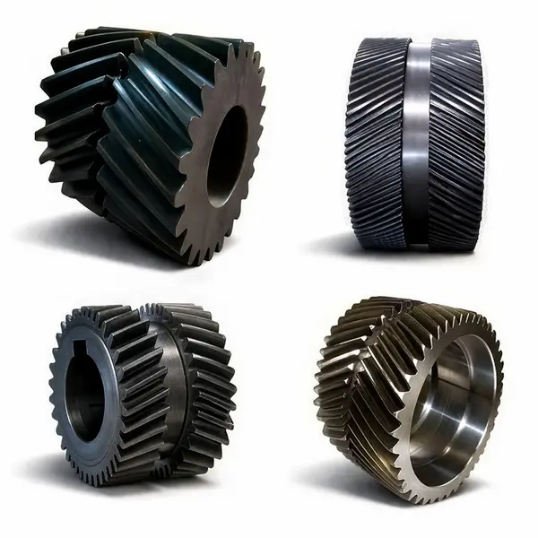
Opposing left/right helix sections cancel axial forces internally — zero net shaft thrust. The preferred choice for ball mill main drives, marine reduction gearboxes, and offshore winches transmitting >500 kNm where thrust-bearing simplification is critical.
View Product Details
Precision ground to 15° and 19°31' helix angles — optimised contact ratios for smooth, high-load transmission with minimised vibration. HÖFLER ground to Ra 0.3–0.6 μm for CNC machine tool spindles, high-speed industrial gearboxes, and NVH-critical drive applications.
View Product Details
POM (Delrin) and Nylon 66 helical gears, module M0.1–M2.0, for quiet light-duty drives in office automation, medical devices, instruments, and consumer appliances. Lightweight, self-lubricating, and corrosion-resistant — no lubrication required in many applications.
View Product Details
The standard configuration for industrial gearboxes, motor reducers, and conveyor drives where both shafts run parallel. Available module M1–M50 in soft tooth (HB 220–280) and hard tooth (HRC 58–62) variants. Covers the complete range from compact instrument gears to large mill pinions.
View Product Details
Transmits motion between non-parallel, non-intersecting shafts at any crossing angle — including 90°. Point-contact tooth mesh delivers inherently quiet operation. Specified for camshaft drives in IC engines, CNC auxiliary axes, elevator governor mechanisms, and position-adjustment drives.
View Product Details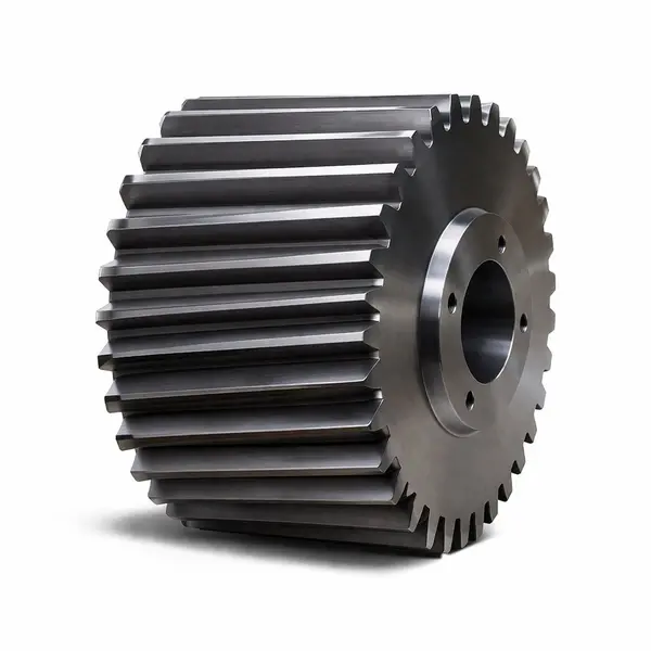
18CrNiMo6 press-forged blank, gas-carburized to HRC 58–62 case, HÖFLER ground to DIN Class 6. Engineered for the high-impact, shock-loaded duty cycles of ball mill pinions, crusher gearboxes, and underground mining machinery where fatigue life and surface durability are non-negotiable.
View Product DetailsHow Helical Gears Work

Progressive Diagonal Engagement
Each tooth enters mesh at a single point on the leading edge, and the contact line sweeps diagonally across the face. Load builds gradually from zero to peak — eliminating the instantaneous impact load that makes spur gears noisy and prone to fatigue under variable torque.
Multi-Pair Load Sharing
A gear pair with β = 25° achieves a total contact ratio of 2.5–3.5 — meaning 2.5 to 3.5 tooth pairs carry load simultaneously at any mesh position. This translates directly to 25–50% higher torque transmission in the same gear diameter and material grade.
Axial Thrust and the Double Helical Solution
The helix generates an axial force = Ft × tan β. For single helical gears, thrust bearings handle this. For double helical gears, opposing-hand helix sections cancel axial forces internally — producing zero net axial force. This is why herringbone gears are standard in ball mills and large marine gearboxes.
EHL Film and Tooth Finish
At the tooth contact, an elastohydrodynamic (EHL) oil film separates the steel surfaces. A ground tooth flank (Ra ≤ 0.6 μm) maintains this film more reliably than an as-hobbed surface (Ra ≈ 3.2 μm), suppressing pitting initiation and extending contact fatigue life by 3–5×.

Helical Cut Gear vs Spur Gear — The Engineering Case
When engineers compare the two gear types across noise, load capacity, and speed range, the helical tooth form wins on every performance metric except axial thrust.


| Performance Parameter | Spur / Straight Cut Gear | ✦ Helical Cut Gear |
|---|---|---|
| Tooth Engagement | Simultaneous full-width — impulse loading | ✔ Progressive diagonal — gradual loading |
| Total Contact Ratio | 1.2–1.6 (transverse only) | ★ 2.0–4.5 (transverse + overlap) |
| Noise at 1500 RPM | 78–85 dB(A) typical | ✔ 66–74 dB(A) — up to 12 dB quieter |
| Axial Thrust | None (zero axial force) | Present — managed by bearings or double-helix |
| Torque Capacity | Baseline | ★ 25–50% higher for same pitch diameter |
| Speed Range | Up to ~10 m/s typical | ✔ Up to 150 m/s (ground, turbine drives) |
| Vibration | High — abrupt mesh excitation | ✔ Low — smooth force variation |
| Mesh Efficiency | 97–98% | 98–99.5% (ground variants) |
Helical Gear Applications — Where They Excel
The combination of high load capacity, low noise, and wide speed range makes this gear type the first choice across industries that demand reliability in a compact power envelope.

Heavy Industrial Drives
Conveyor gearboxes, rolling mill pinions, crusher drives, and compressor reducers. Carburized 18CrNiMo6 gears in module M8–M30 running 20,000+ service hours between overhauls. The high contact ratio distributes sudden shock loads across more tooth pairs, significantly extending mean time between failures in continuous production.
CNC Machine Tools
Spindle gearboxes and feed-axis reducers specify DIN Class 4–6 ground gears in 20CrMnTi. Transmission error directly correlates with workpiece surface finish: ground helical gears reduce transmission error amplitude by 60–80% compared with hobbed gears of the same module, allowing higher cutting speeds without chatter initiation.
Railway Traction
High-speed train traction gearboxes use 17CrNiMo6 carburized gears at DIN Class 6 with β = 18°. Korea Ever-Power's traction gear series is designed to KTX and UIC railway certification requirements, including Charpy impact at −30°C and permanent traceability marking for lifecycle tracking.
Mining & Mineral Processing
Ball mill pinions (M12–M45, OD up to 2500mm) in forged 18CrNiMo6 with hard carburized tooth flanks. Double helical configuration eliminates axial thrust in mill ring gear drives, enabling simpler main bearing arrangements and reducing catastrophic bearing failure risk in remote installations.
Food, Beverage & Packaging
Bottling and packing lines specify β = 45° gears in 20CrNiMoA to suppress mesh noise below 70 dB(A) in operator zones. Stainless steel grades (SS304/SS316) are available for open-gear positions subject to wash-down water and sanitising chemical contact, meeting EU Machinery Directive noise exposure limits.
Automotive & EV Drive Systems
All modern passenger car gearboxes use helical gears exclusively for NVH reasons. In electric vehicle single-speed reduction units, the entire speed range must meet strict acoustic targets — helical gears running in grease-lubricated housings achieve these at substantially lower cost than hypoid or planetary alternatives while delivering 98–99.5% mesh efficiency.
Technical Specification Range
Korea Ever-Power's in-house capability covers the widest practical parameter range available from a single Korean supplier — from sub-millimetre fine-pitch instrument gears to 2.5-metre diameter heavy industrial ring gears.
Extended ranges, non-standard pressure angles, profile shifts, crowning, and asymmetric tooth profiles are available on request after a technical feasibility review.
| Parameter | Standard Range | Notes |
|---|---|---|
| Normal Module (Mn) | M1 – M50 | M50+ on enquiry |
| Helix Angle (β) | 5° – 45° | Matched pairs for double helical |
| Pressure Angle | 14.5°, 20°, 22.5°, 25° | Custom angles available |
| Outer Diameter | 20 mm – 2500 mm | Hobbing ≤1250mm; grinding ≤2500mm |
| Face Width | Up to 1480 mm | Tooth grinding; milling up to 500mm |
| Accuracy (DIN 3962) | Class 3 – 9 | Class 5–6 standard production |
| Tooth Flank Ra | 0.3 – 3.2 μm | Ra 0.3 (precision ground) |
| Hard Case (Carburized) | HRC 58 – 62 | 20CrMnTi / 17CrNiMo6 |
| Induction Hardened | HRC 40 – 55 | 42CrMo, 40Cr |
| Material Grades | 45# / 40Cr / 42CrMo / 20CrMnTi / 17CrNiMo6 / SS304 | DIN/ASTM/JIS equivalents |
| Sample Lead Time | 15 – 25 working days | Depends on size & heat treatment |
* Module M50+, OD > 2500mm: available via partner facilities. Contact engineering team.
Our Manufacturing Process

Key Considerations in Gear Selection
Four engineering decisions to make before submitting an RFQ — getting these right on paper saves time and cost downstream.

Shaft Arrangement
Parallel shafts → single or double helical gear. Intersecting at 90° → helical bevel. Non-parallel, non-intersecting → crossed helical (screw gear). Getting the gear type wrong means redesigning the entire drive layout.
Load & Speed Profile
Steady moderate torque → soft tooth flank QT (HB 220–280). High-cycle or shock-loaded drives → carburized hard tooth (HRC 58–62). Specifying carburizing for a slow conveyor drive adds cost without benefit.
Precision Grade
NVH-critical (railway, CNC, packaging) → DIN Class 4–6, ground. General conveyor, mill auxiliary drives → Class 7–9, hobbed. Over-specifying Class 5–6 for a conveyor adds 30–40% cost with no performance gain.
Operating Environment
Enclosed gearbox in clean environment → carbon/alloy steel. Marine spray, food wash-down, chemical → SS304/SS316. Agricultural, mining → induction-hardened 42CrMo for the combination of shock toughness and surface hardness.
What Sets Our Manufacturing Apart
Full In-House Capability
Forging, rough machining, heat treatment, tooth grinding, MPI, CMM inspection, and packaging all at our Ansan-si facility. No outsourcing of critical process steps — no quality gaps between suppliers.
German HÖFLER Grinding
HÖFLER gear grinding machines achieve DIN Class 3–5, Ra 0.3–0.6 μm — the same equipment platform used by European precision gear manufacturers for aerospace and railway-grade components.
Complete Documentation
Every gear: material certificate (heat number, chemical analysis, mechanical properties), hardness test record, gear analyser report (profile/lead/pitch per DIN 3962), MPI certificate, and CMM dimensional report.
Reverse Engineering Service
No drawing? Send the worn gear. OES spectrometer identifies material grade. Gear analyser measures all tooth parameters. Matched replacement in 15–25 working days — standard service for mining, mill, and marine maintenance customers.
Korean & Regional Supply Chain
Proximity to Korean automotive OEMs, Hyundai Heavy Industries, POSCO, and Korean rail operators means faster delivery, easier technical communication, and direct site visits for qualification audits.
Fast-Track Urgent Orders
Mill-down and production-stop situations receive priority scheduling. Standard modules in common materials can ship in 10–14 working days with a confirmed delivery date at order placement.
Frequently Asked Questions — Helical Gear
A straight-cut (spur) gear has teeth parallel to the shaft axis. All tooth contact begins and ends simultaneously across the full face width — creating an impulse load that produces noise and high dynamic load factors at speeds above ~8 m/s.
A helical cut gear has teeth inclined at the helix angle β. Contact begins at one tooth end and sweeps progressively across the face, so load builds gradually rather than instantaneously. The result: 8–12 dB(A) lower noise, 25–50% higher load capacity, and significantly lower vibration levels. The trade-off is an axial force component that must be managed by thrust bearings, or cancelled by using a double helical (herringbone) configuration.
- β = 8°–15°: Where axial thrust must be strictly limited — long unsupported shafts or bearings with low axial capacity. Contact ratio improvement is modest.
- β = 15°–25°: The practical optimum for most industrial drives — substantial noise reduction (−8–10 dB), manageable axial force handled by standard angular-contact bearings.
- β = 25°–35°: High-performance machine tool spindles, automotive gearboxes. Maximum contact ratio for given face width. Requires thrust-capable bearing arrangement.
- β = 45°: Packaging and beverage machinery where noise minimisation is the primary design target. Generates substantial axial thrust — pair with opposing-hand helical stage or use double helical design.
If axial thrust is a problem, specify a double helical design at β = 25°–30° per hand — you gain both the contact ratio benefit of a large helix angle and net-zero axial force at the shaft.
A double helical gear — also called herringbone gear — has opposing left-hand and right-hand helix sections on the same body, separated by a central relief groove. Their axial forces cancel internally, producing zero net axial force at the shaft and bearings.
Specify double helical gears when: transmitted torque is high enough that single helical thrust would require large/expensive thrust bearings; gearbox housing space is constrained; or you want the noise benefit of a large helix angle without the axial force penalty. Korea Ever-Power manufactures double helical gears as matched gear pairs confirmed from a single manufacturing run.
Gear hobbing (helical gear milling) uses a rotating multi-flute hob that traverses axially while both hob and blank rotate in synchrony. The most productive method for external helical gears. The hob axis is tilted at the helix angle + hob lead angle to generate the correct spiral.
Gear shaping uses a gear-form cutter that reciprocates axially while rotating in mesh with the blank. The only practical method for internal helical gears, and for external gears with a shoulder that prevents hob over-run. Both processes achieve DIN Class 8–9 as-cut. For Class 3–6, subsequent heat treatment and grinding on HÖFLER equipment corrects distortion and achieves the final accuracy.
- 45# carbon steel (QT): Low-cost option for slow-speed, low-duty drives. HB 220–260.
- 42CrMo (QT or induction hardened): Workhorse for agricultural, mining, and heavy industrial gears needing shock resistance + moderate surface hardness (HRC 40–50). ASTM 4140 equivalent.
- 20CrMnTi (carburized): Automotive, EV, and machine tool gears requiring HRC 58–62 and high contact fatigue life. Close to DIN 20MnCr5.
- 17CrNiMo6 / 18CrNiMo6 (carburized): Railway traction, offshore drives — HRC 58–62 surface + Charpy impact resistance at sub-zero temperatures.
- SS304 / SS316: Food processing, pharmaceutical, marine open-gear, chemical environments. Lower load ratings but excellent corrosion resistance.
Advantages:
- 8–12 dB(A) lower noise than spur gears at equivalent speed and load
- 25–50% higher load capacity in the same gear envelope
- Suitable for pitch-line velocities up to 150 m/s (ground, turbine-grade)
- Smoother torque transmission reduces vibration and dynamic load factors
- Double helical variant eliminates axial thrust entirely
Disadvantages:
- Generates axial thrust force (single helical only) — requires thrust-capable bearings
- Slightly higher manufacturing cost vs spur gears
- Double helical requires precise helix phase matching — more complex tooling and setup
For the vast majority of industrial applications above 1 m/s pitch-line velocity, the advantages substantially outweigh the disadvantages.
A helical gear is a single manufactured component that requires a housing, shafts, bearings, and seals to function in a drive system. A helical gearbox (or helical gear reducer) is a complete, self-contained power transmission unit including all of these elements — ready to bolt onto a machine and couple to a motor. Available in single-stage (ratios ~1.5:1 to 8:1) and multi-stage (up to 1000:1) configurations.
Korea Ever-Power supplies both loose gears for OEM customers who build their own gearbox housings, and assembled helical gearbox units for customers who need a bolt-on solution. Contact our engineering team with your torque, ratio, speed, and mounting requirements.
- Small gears (M1–M12, OD ≤ 200mm) in stock materials: 15–20 working days
- Medium industrial gears (M12–M30) with carburizing: 4–6 weeks
- Large cast-steel gears (OD > 500mm): 8–14 weeks
For urgent replacement orders (mill-down, vessel in dry dock), contact us immediately with your required delivery date — we will confirm the fastest achievable schedule based on current production loading. If raw material is in our warehouse, 10–14 working days is achievable for standard modules.
Quick Reference
Questions covering the most common technical and procurement considerations for helical gears — or contact our engineers directly for application-specific guidance.
💡 No drawing? Send us the worn gear — we measure, confirm material by OES spectrometer, and manufacture a matched replacement in 15–25 working days.
Engineering Blog & Guides
What Our Customers Say
17CrNiMo6 DIN Class 6 gears for metro bogie gearboxes. Full documentation package — material certs, Charpy impact at −30°C, gear measuring reports. Every dimension within tolerance. Classification society surveyor passed inspection on the first visit.
Rebuilt a CNC spindle head with ground DIN6 gears. Workpiece surface finish improved by ~15% on profilometer readings — attributed directly to lower transmission error from the precision gears. Competitive price versus local suppliers and shorter lead time than expected.
SAG mill pinion needed manufacturing from drawing in 18 working days — Korea Ever-Power confirmed and delivered on schedule. Now at 600 operating hours with no abnormal wear. Permanent traceability marking satisfied our mining OEM audit requirements.
Get Your Custom Quotation in 24 Hours
Send a drawing, worn sample, or key parameters. Our engineers confirm feasibility, material selection, and delivery timeline — at no obligation.


