
Ground Helical Gears — Precision-Ground 15° and 19°31′ for Smooth, High-Load Transmission

Korea Ever-Power ground helical gears are produced in 15° and 19°31′ helix angles, left-hand and right-hand, with transverse module 1 and up to 100 teeth on the reference series (bore 15mm, pitch diameter 100mm, total length 18mm). Tooth grinding produces a consistently finer surface finish than gear hobbing or shaping, supporting higher contact loads and quieter high-speed operation. A matched left-hand and right-hand 15° pair can directly replace spur gears in most parallel-shaft applications where reduced noise is the objective.
Ground Helical Gear — Overview
A ground helical gear is a helical cut gear whose tooth flanks have been finish-ground after hobbing or shaping, rather than left in the as-cut condition. Grinding removes the tool marks left by the hob or shaper cutter and corrects minor errors in tooth profile and lead introduced during the cutting operation. The result is a smoother tooth surface — typically Ra 0.4–0.8 µm compared to Ra 1.6–3.2 µm for a well-hobbed gear — which reduces sliding friction between mating teeth, lowers operating temperature, and extends fatigue life under cyclic loading.
Korea Ever-Power Worm Gear Co.,Ltd produces ground helical gears in two standard helix angle variants: 15° and 19°31'. Both are available in left-hand and right-hand configurations. The 15° series is designed as a direct substitute for straight spur gears in applications where the existing shaft geometry already suits the small amount of axial force a 15° helix produces. The 19°31' series is matched to run with gear racks of the same helix angle, covering applications in linear motion systems, machine tool tables, and positioning drives where the rack-and-pinion combination must engage smoothly without lead error. Replacement configurations compatible with standard metric precision gear catalogs are available — provide your existing part number or drawing for a cross-reference.
Technical Specifications
The reference specification below applies to the Module 1, 100-tooth, left-hand ground helical gear series. Korea Ever-Power also supplies this design in right-hand configuration; a matched pair of opposite-hand gears will rotate two parallel shafts in opposite directions. Custom tooth counts, bore sizes, and hub dimensions are available on request.
Module 1, 100 Tooth, Left Hand, Ground Helical Gear — Reference Data
| Parameter | Value |
|---|---|
| Bore Type | Ground |
| Transverse Module | 1 |
| No. of Teeth | 100 |
| Direction of Helix | Left Hand |
| Shape | S1 |
| Bore (A) | 15.0 mm |
| Hub Diameter (B) | 50.0 mm |
| Pitch Diameter (C) | 100.00 mm |
| Outer Diameter (D) | 102.00 mm |
| Face Width (E) | 8.0 mm |
| Hub Width (F) | 10.0 mm |
| Total Length (G) | 18.00 mm |
| Helix Angle | 21°30' |
| Pressure Angle | 20° |
Ground vs Hobbed Helical Gear — What the Difference Means in Practice
Both hobbed and ground helical cut gears start from the same blank and the same tooth form, but the manufacturing process diverges at the finishing stage. Hobbing removes material efficiently with a worm-type multi-tooth cutter and is the standard process for general-purpose gears. Grinding uses abrasive wheels to correct the residual errors in tooth profile and lead that hobbing leaves behind. The table below summarizes the practical differences between the two processes at the level of detail that matters for gear performance.
| Parameter | Hobbed Helical Gear | Ground Helical Gear |
|---|---|---|
| Tooth surface finish (Ra) | 1.6–3.2 µm | 0.4–0.8 µm |
| ISO 1328 accuracy class (typical) | ISO 7–9 | ISO 4–6 |
| Allowable contact stress (same material) | Moderate | Higher — surface integrity from grinding reduces pitting initiation sites |
| Noise at high speed | Audible harmonic mesh tone increases with speed | Lower mesh tone; profile accuracy reduces transmission error excitation |
| Run-in period required | Typically 40–100 hours at partial load | Shorter or none — contact pattern is correct from first mesh |
| Unit cost | Lower | Higher — additional process step adds cost and lead time |
| Typical applications | General industrial drives, low to moderate speed | Machine tools, servo drives, turbine gearboxes, precision instruments |

15° vs 19°31' Helix Angle — Choosing the Right Series
The two helix angle options offered in the Korea Ever-Power ground helical gear range are not interchangeable — each is optimized for a specific engagement geometry. Selecting the wrong angle series for a given application will result in a lead error at the mesh, elevated noise, and uneven load distribution across the face width.
15° Ground Helical Gear Series
The 15° series is engineered as a spur gear substitute. A 15° helix angle produces a small axial force component — roughly 27% of the tangential load — which is manageable with standard deep-groove bearings without thrust preloading. The gradual diagonal tooth contact gives a measurably smoother torque curve and lower noise floor compared with a spur gear of the same module and tooth count. A matched pair of left-hand and right-hand 15° gears will rotate parallel output shafts in opposite directions, which suits applications where counter-rotation is needed. For instrument drives, light machine tool heads, and benchtop precision equipment, the 15° ground series offers an easy upgrade path from spur gears without gearbox housing redesign.
19°31' Ground Helical Gear Series
The 19°31' series is designed to mesh with gear racks manufactured to the same helix angle. This angle is a recognized standard in the precision gear rack industry — it was established so that the rack tooth form and the pinion tooth form, when both are ground to the same helix angle, produce a theoretically perfect involute contact. Machine tool table drives, gantry positioning systems, and robotic linear axes that use precision ground racks should use 19°31' ground pinions to achieve the smooth, low-backlash motion these applications demand. Mismatching the pinion angle with a standard 15° series or an unhelical spur pinion on a 19°31' rack will introduce transmission error and shorten rack and pinion service life.
Key Advantages of Grinding for Helical Gears
✦ More Accurate Tooth Profile
Precision ground helical gears achieve a tighter tooth profile than machined or cut gears, providing smoother mesh and more controlled motion output — critical for servo-driven axes and instrument transmissions.
✦ Broader Material Compatibility
Grinding works on hardened materials that cannot be hobbed after heat treatment. This means the gear can be carburized or through-hardened first, then ground to final dimensions — combining maximum core toughness with a hard, wear-resistant tooth surface.
✦ Higher Load and Torque Capacity
Ground helical gears handle higher contact stresses than cut gears of equivalent size. The finer surface finish reduces asperity stress concentrations that nucleate pitting, allowing them to operate closer to the material's fatigue strength limit in high-torque applications.
✦ Reduced Run-In Time
Because the contact pattern is already optimized at the grinding stage, ground helical gears can often be run at full load immediately after installation. Hobbed gears typically require a break-in period of 40–100 operating hours at reduced load to smooth high spots before full-load operation.

Precision Grades and Inspection
Gear accuracy is specified by international standards including ISO 1328, AGMA 2000, DIN 3961, and JIS B 1702. These standards define tolerance bands for total profile error, lead error, pitch deviation, and runout. Korea Ever-Power ground helical gears are manufactured to ISO 1328 class 5–6 as standard, with ISO class 4 available on request for the highest-precision applications.
- ◉ ISO class 5: Total profile deviation ≤ 8 µm (module 1). Suitable for CNC machine tool drives, robotic joints, and high-accuracy linear motion systems.
- ◉ ISO class 6: Total profile deviation ≤ 11 µm (module 1). Standard for general precision gearboxes, servo drives, and instrument transmissions.
- ◉ Inspection equipment: Each ground gear is checked on a gear measuring center (GMC) for tooth profile, lead, pitch, and runout. Measurement reports are available on request.
- ◉ Surface finish: Tooth flank Ra is verified by profilometer. Material certificates and hardness test records are provided with each batch.

Typical Application Scenarios
CNC Machine Tool Spindle and Feed Drives
In machining centers and turning machines, the spindle drive and feed axis gearboxes demand low transmission error across a wide speed range. Transmission error — the deviation from perfectly uniform motion — appears as surface finish marks on machined parts. Ground helical gears at ISO class 5 or 6 minimize transmission error by correcting the tooth profile errors that hobbed gears carry. The 15° helix angle series is used where the small axial force is acceptable; the 19°31' series pairs with precision racks on the machine's linear axes.
Servo Gearboxes and Robotic Joints
Servo systems respond dynamically to position commands and any transmission error appears in the position feedback loop as a tracking error. Robotic arm joints, pick-and-place heads, and precision welding positioners use helical cut gears with ground tooth flanks because the low transmission error allows the servo controller to maintain tight position accuracy without running high-gain corrections that would otherwise excite mechanical resonances.
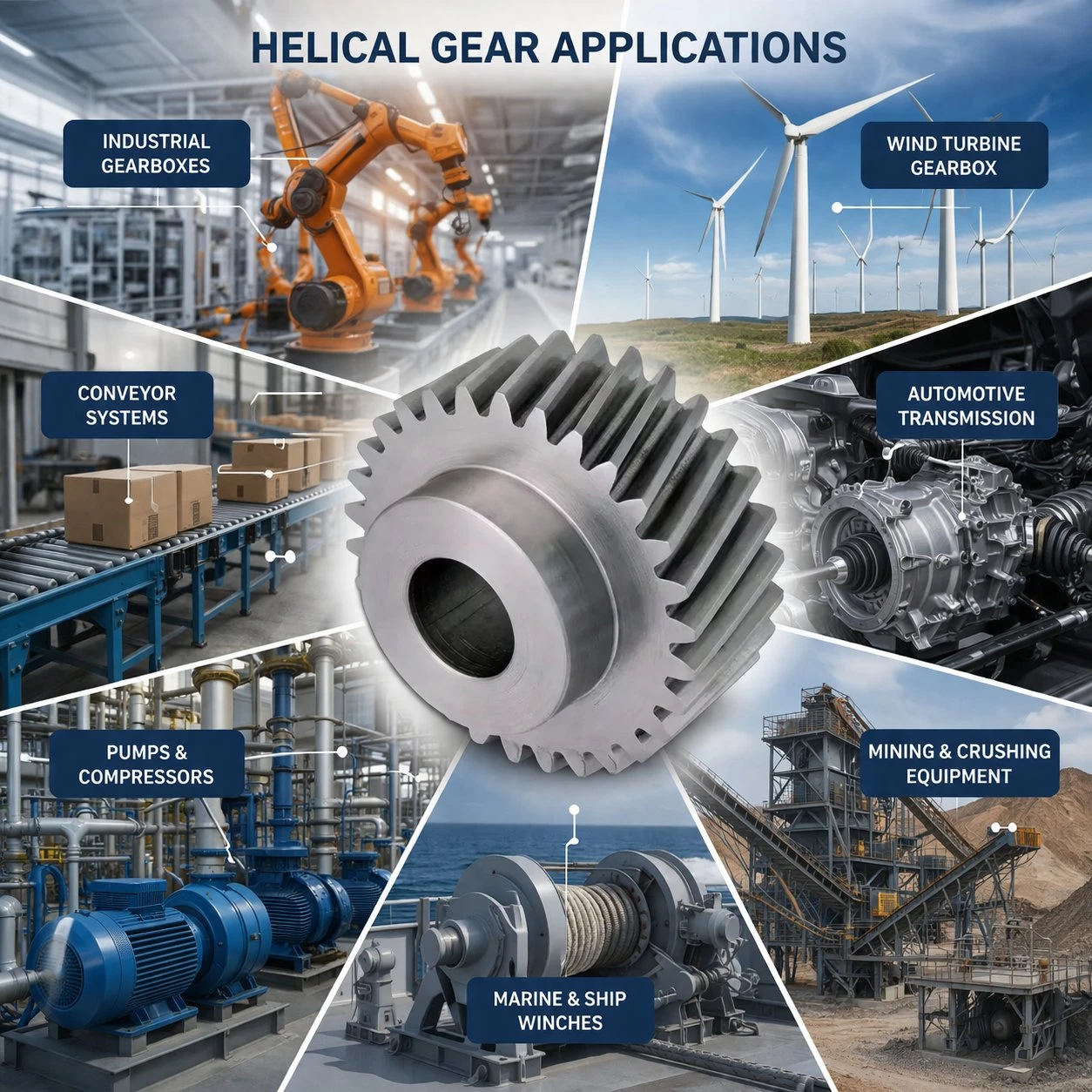
Precision Measuring and Optical Instruments
Coordinate measuring machines (CMM), optical comparators, and microscope stage drives use very fine-module gear pairs where any irregularity in tooth form translates directly into a positioning error. Module 1 or smaller ground helical gears with sub-micron surface finish and tight pitch tolerances are the standard gear type for these applications. The smooth tooth surface also reduces audible noise in laboratory environments.
Related Drive Components
- ➜ Helical Gear Catalog: Browse the full range of helical gear manufacturer products including hobbed, shaved, and ground variants across multiple modules and materials.
- ➜ Worm Gear: For applications where a right-angle drive or large reduction ratio in a compact package is needed, a worm gear can complement a precision helical first stage. Contact us for multi-stage gearbox design support.
- ➜ Double Helical Gear: Where higher torque is needed without axial thrust, see the double helical gear series with paired left/right helices for zero net bearing axial load.

Frequently Asked Questions
What accuracy class do ground helical gears achieve?
Korea Ever-Power ground helical gears are produced to ISO 1328 class 5–6 as the standard offering. ISO class 4 is available for applications with the most demanding transmission error requirements. Hobbed gears typically reach class 7–9, so grinding provides a meaningful improvement in geometric accuracy.
Can a 15° ground helical gear replace a spur gear without modifying the gearbox housing?
In most cases, yes — provided the center distance, bore diameter, and module are identical. The 15° helix produces a modest axial force (approximately 27% of tangential load) that standard deep-groove bearings can absorb without modification. If the existing bearings are already running near their dynamic load rating, it is worth verifying that the additional axial component remains within the bearing's combined load capacity before proceeding.
Why is the 19°31' helix angle used with gear racks?
The 19°31' angle is an established standard for precision ground rack-and-pinion systems. Both the rack and the pinion tooth flanks are ground to this same helix angle, producing conjugate involute contact and minimizing transmission error along the rack stroke. Using a pinion with a different helix angle on a 19°31' rack creates a lead mismatch that distributes load unevenly across the face width and increases noise and wear.
What materials are ground helical gears available in?
The reference series is produced in case-hardened alloy steel. Because grinding removes material after heat treatment, a wide range of alloy steels can be used: 20CrMnTi (carburized, HRC 58–62 case), 42CrMo (through-hardened, HRC 48–54), and SCM415/SCM440 equivalents for Japanese-standard specifications. Stainless steel grinding is available for corrosion-sensitive environments such as food-processing equipment and medical devices.
How do I specify a ground helical gear for a rack-and-pinion linear axis?
Provide the rack module (Mn), rack helix angle (must match the pinion — 19°31' for standard precision racks), pinion tooth count, required shaft bore diameter and keyway, face width, and the accuracy class needed for the positioning resolution of the axis. For high-duty-cycle linear drives, also specify the expected number of rack passes per year so that the correct material and heat treatment can be recommended.
What lubrication is recommended for ground helical gears in precision machine tool applications?
For enclosed precision gearboxes, a synthetic PAO gear oil ISO VG 100–150 is preferred — it maintains stable viscosity over a wide temperature range and contains fewer polar additives that can stain the precision ground surfaces. For open rack-and-pinion drives on machine tools, a tacky grease (NLGI grade 1–2) with EP additives is applied to the rack at the lubrication interval recommended by the machine builder, typically every 4–8 operating hours.
What is the lead time for custom ground helical gears?
Standard module and tooth-count combinations in the reference series: 2–3 weeks. Custom bore, non-standard module, or special accuracy requirements: 4–6 weeks from drawing approval. For urgent prototype orders, contact Korea Ever-Power to discuss expedited scheduling. All lead time commitments are confirmed in writing after design review.
Customer Reviews
Lee Joon-seok, CNC Applications Engineer, Changwon Manufacturing Hub (Q4 2024)
"We upgraded the feed gearbox of a vertical machining center using module 1, 60-tooth ground helical gears from Ever-Power. The surface finish on the gear blanks was noticeably better than the parts we sourced locally. Machined part surface quality improved — we attribute most of that to reduced transmission error. No complaints after four months of three-shift operation."
Tanaka Hiroshi, Design Engineer, Osaka Precision Equipment (Q2 2024)
"I specified 19°31' left-hand ground helical pinions to pair with our standard ground racks on a gantry positioning system. Korea Ever-Power confirmed the helix angle match and delivered with a gear measurement report. The backlash on the new pinions was within our spec of 0.03 mm. Very satisfied with the documentation and dimensional accuracy."
Jung Yoo-jin, Procurement Engineer, Seoul Robotics Components (Q3 2024)
"We use 15° ground helical gears in the shoulder joints of our collaborative robot arm. Noise level matters to our customers — the Ever-Power gears run about 3 dB quieter than the previous hobbed parts we were using, which is clearly noticeable in a quiet workspace. Bore tolerance was H6 as specified. Will order again."
Oh Byung-won, Senior Engineer, Daejeon Instrument Lab (Q1 2025)
"Ordered ground helical gears for a coordinate measuring machine stage drive. The parts came with a full measurement sheet — profile, lead, pitch, and Ra. Everything was within ISO class 5 tolerances. The gear measuring center report saved us two days of incoming inspection. Good communication throughout the order."
Lim Kian Huat, Technical Manager, Penang Automation Systems (Q2 2024)
"We switched from a European supplier to Korea Ever-Power for our servo gearbox pinions. Lead time dropped from 8 weeks to 3.5 weeks, and the price was about 20% lower. Quality checks out — we have been running the same gears for ten months without any tooth wear issues. The right-hand and left-hand pair arrived correctly matched."
Additional information
| Editor | Cxm |
|---|
Related products
-
Rolling Mill Double Helical Gear — Split Assembly or Integral Herringbone
-

Medical Double Helical Gear — Metal Grade Fine-Pitch Herringbone Gears for Diagnostic and Military Precision Drives
-

Heavy Machinery Double Helical Gear — Cast Steel Soft Tooth Flank, QT, ISO Grade 8–9
-

High Speed Train Locomotive Hard Tooth Flank Helical Gear — DIN Class 6 for Traction Drives
-

Beverage Packing Machinery Helical Gear — AGMA Class 8 for Ultra-Quiet High-Speed Packaging Drive
-

Soft Tooth Flank Helical Gear — DIN Class 6 for Rolling Mill Auxiliary Drives
-

Parallel Axis Helical Gears — High-Speed Heavy-Load Transmission for Parallel Shaft Systems
-
Double Helical Gear — Zero Axial Thrust for High-Torque Parallel Shaft Drives


























