
Crossed Helical Gear (Screw Gear) — Non-Intersecting Shaft Transmission with Flexible Axis Angles

Crossed helical gears, also called screw gears, transmit motion between non-intersecting, non-parallel shafts at arbitrary shaft angles — unlike parallel helical gears which are limited to parallel shafts. The shaft angle equals the sum of the two helix angles when no profile shift is applied. Contact between mating teeth is a point (not a line), so these gears are suited for light-to-moderate load applications: machine tool auxiliary drives, camshaft drives in small IC engines, elevator ancillary mechanisms, and instrument positioning systems. Modules M1–M12, precision DIN6–DIN9, multiple material grades available.
Crossed Helical Gear (Screw Gear) — Overview
Crossed helical gears — sometimes called screw gears — are a specialized form of helical cut gear designed to transmit motion and force between two shafts that neither intersect nor run parallel to each other. In a standard parallel axis helical gear pair, both gears share the same helix angle but carry opposite hands. In a crossed helical arrangement, both gears may carry the same hand of helix, and the shaft crossing angle is determined by the sum (or difference) of the individual helix angles. This flexibility allows the designer to set almost any shaft angle between the driving and driven shafts without resorting to bevel or worm arrangements — a meaningful option when space or shaft layout constraints make a right-angle or near-right-angle parallel drive impossible.
The key limitation that distinguishes crossed helical gears from their parallel axis equivalents is contact type: while parallel axis helical gears develop line contact as tooth pairs come fully into mesh, crossed helical gears maintain only point contact throughout the entire engagement cycle. Point contact means a smaller effective load-bearing area per tooth pair, which limits these gears to light and moderate torque applications. For heavy-load drives, parallel axis or double helical configurations are more appropriate. Korea Ever-Power Worm Gear Co.,Ltd supplies crossed helical gears in modules M1 to M12 across multiple material grades, with precision levels from DIN6 to DIN9 and a comprehensive range of surface treatments for export to Korea and neighboring markets.
Technical Specifications
Korea Ever-Power crossed helical gears are manufactured to the following standard parameter range. Custom helix angles, non-standard modules, and special shaft-angle-specific configurations are available upon submission of a drawing or application data.
| Parameter | Specification |
|---|---|
| Model Number | M1, M1.5, M2, M2.5, M3, M4, M5, M8, M12 and etc. |
| Material | Brass, C45 steel, Stainless steel, Copper, POM, Aluminum, Alloy, and so on |
| Surface Treatment | Zinc-plated, Nickel plated, Passivation, Oxidation, Anodization, Geomet, Dacromet, Black Oxide, Phosphatizing, Powder Coating, Electrophoresis |
| Standard | ISO, DIN, ANSI, JIS, BS and Non-standard |
| Precision | DIN6, DIN7, DIN8, DIN9 |
| Teeth Treatment | Hardened, Milled, or Ground |
| Tolerance | 0.001mm – 0.01mm – 0.1mm |
| Finish | Shot/sandblast, heat treatment, annealing, tempering, polishing, anodizing, zinc-plated |
| Items Packing | Plastic bag + Cartons or Wooden Packing |
| Payment Terms | T/T, L/C |
| Production Lead Time | 20 business days for sample, 25 days for bulk |
| Application | Machine tools, semiconductor equipment, camshaft drives, lift/elevator mechanisms, solar energy equipment, parking systems, instrumentation |
How Crossed Helical Gears Work — Screw Motion and Point Contact

The Screw Motion Engagement Mechanism
In a parallel axis helical gear pair, the pitch cylinders of the two gears roll on each other without sliding — pure rolling exists at the pitch point. In a crossed helical gear pair, no such pure rolling point exists anywhere on the reference bodies. Instead, the motion of one tooth flank relative to the other is a continuous screw motion throughout the entire engagement arc. The technical term for the reference bodies of crossed helical gears is rotational hyperboloids, formed by rotating a skew line around an axis. The screw motion means the tooth flanks continuously slide against each other, generating more heat and friction than an equivalent parallel axis gear pair. This is why crossed helical gears require careful lubrication — typically with hypoid gear oil or similar EP lubricants — and why their efficiency is lower than parallel axis configurations at equivalent load levels. A well-lubricated crossed helical gear pair can achieve efficiencies of 70–90% depending on the helix angles and contact geometry; parallel helical gears reach 97–99% in comparison.
Axial Adjustability — A Useful Practical Property
One practical property that distinguishes crossed helical gears from most other gear types is their tolerance for axial displacement. Because the contact is always a point regardless of the relative axial position of the two gears, either gear can be shifted axially within a relatively wide range without disrupting the transmission. This property is exploited in applications such as backlash adjustment mechanisms, where one gear is shifted axially against a spring load to maintain near-zero backlash as the teeth wear. It also simplifies assembly in tight shaft arrangements where axial positioning tolerance cannot be held as tightly as center distance tolerance.
Parallel Helical Gear vs Crossed Helical Gear — Direct Comparison

The decision between a parallel axis and a crossed helical configuration is primarily driven by shaft geometry and load level. The comparison below covers the key engineering parameters that differentiate the two types — drawn from the original technical content and expanded with practical context.
| Parameter | Parallel Helical Gear | Crossed Helical Gear |
|---|---|---|
| Shaft configuration | Parallel shafts only | Non-intersecting, non-parallel shafts at arbitrary angles |
| Helix angle pairing | Same angle, opposite hands | Different angles; same or opposite hands depending on shaft angle |
| Contact type | Starts at point, becomes line contact | Point contact throughout engagement |
| Load capacity | High — suitable for heavy-duty drives | Light to moderate — point contact limits Hertzian stress capacity |
| Efficiency | 97%–99% | 70%–90% — continuous flank sliding reduces efficiency |
| Lubrication requirement | Standard gear oil | EP or hypoid gear oil required for flank sliding protection |
| Axial adjustability | Limited — center distance is fixed | Wide axial shift range without affecting transmission quality |
| Noise level | Low | Low — point contact and screw motion both suppress impact noise |
Design Considerations for Crossed Helical Gears

Designing a crossed helical gear drive requires attention to several parameters that are less critical in parallel axis systems. Getting these right during the specification stage prevents premature wear, overheating, and unexpected shaft loading.
- ◈ Shaft crossing angle: The shaft angle between the two axes equals the sum of the two helix angles (for same-hand helices) or the difference (for opposite-hand helices). Both helix angles must be specified at the design stage; they cannot be adjusted after the gears are manufactured without cutting new gears.
- ◈ Lateral bearing forces: The screw tooth path generates lateral forces perpendicular to both the radial and tangential directions. These forces must be absorbed by the shaft bearings. An angular-contact ball bearing or a combination bearing arrangement is typically required at both gear shaft ends to handle the resultant loads without excessive deflection.
- ◈ Lubrication grade: Standard mineral gear oil is not adequate for the flank sliding speeds typical of crossed helical gear drives. EP (Extreme Pressure) additive gear oils or hypoid gear oils are recommended. The EP additives form a protective layer on the tooth flank surface under sliding contact conditions, preventing adhesive wear at the contact point.
- ◈ Material pairing: Running two steel crossed helical gears against each other is possible but accelerates wear compared to a steel-on-brass or steel-on-bronze pairing. The dissimilar material combination provides better sliding wear resistance. For applications where brass is not suitable, a high-hardness steel gear against a softer steel counter-gear with adequate lubrication is the alternative.
- ◈ Load limitation: Do not apply crossed helical gears to drives where the transmitted torque approaches the capacity of a spur or parallel helical gear of the same size. The point contact constraint means crossed helical gears have roughly 10–30% of the load capacity of an equivalent parallel helical gear. When in doubt, consult Korea Ever-Power with your torque and speed data before finalizing the design.
Typical Application Scenarios

Camshaft and Auxiliary Drives in Small IC Engines
In small internal combustion engines, the camshaft may be driven from the crankshaft via a set of crossed helical gears (screw gears) where a simple 1:2 ratio is needed but the camshaft and crankshaft axes are offset rather than parallel. The smooth engagement of the helical tooth form reduces valve train noise compared with spur gear timing drives, and the low load level of a camshaft drive (torsional resistance from valve springs only, not direct power output) suits the load capacity of a crossed configuration. On small IC engines for powered tools and small generators, the screw motion also provides a slight self-dampening effect on camshaft rotational irregularities.
Machine Tool Auxiliary Mechanisms
CNC machining centers, grinding machines, and multi-axis turning centers contain dozens of auxiliary mechanisms alongside the primary drive system — coolant pump drives, chip conveyor drives, tool-change magazine rotations, and workpiece clamping actuators. Many of these secondary drives need to connect shafts that are not parallel due to the compact packaging of the machine structure. Crossed helical gears provide a compact, quiet solution for these low-to-moderate torque auxiliary paths. The low noise characteristic is particularly valued in high-end machine tools where acoustic performance is part of the product specification. For guidance on specifying the right helical gear type for your machine tool drive, our product catalog is available at helical cut gears product page.
Lift, Elevator, and Escalator Auxiliary Drives
Crossed helical gears appear in elevator and escalator installations for non-primary drives: safety governor drives, door operator mechanisms, and speed indicator drives. The non-reversibility characteristic that some crossed helical arrangements exhibit — where the output shaft cannot back-drive the input under load — provides a passive safety function in governor drives. The compact size of a crossed helical gear pair versus an equivalent bevel gear set is also advantageous in elevator machine rooms where floor space is constrained.
Gear Types We Manufacture — Helical Gears and Beyond

Korea Ever-Power Worm Gear Co.,Ltd supplies a full range of gear types for different shaft configurations and load requirements. If crossed helical gears do not fit your application, the following alternatives may be more suitable:
- ⬡ Parallel Axis Helical Gear: For parallel shaft drives requiring higher load capacity than crossed helical gears can provide. Line contact and high contact ratio for heavy-duty continuous-duty applications.
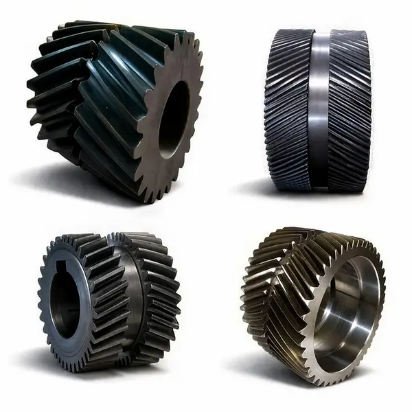
- ⬡ Double Helical Gear: For parallel shaft drives with no axial thrust requirement. The double helical gear series combines left and right helices on one blank to cancel bearing thrust forces, suitable for turbine and marine gearboxes.
- ⬡ Bevel Gear: For intersecting shaft drives (typically 90°) where the shafts actually cross rather than being offset. Higher load capacity than crossed helical gears for right-angle drives.
- ⬡ Worm Gear: For non-intersecting 90° drives requiring high reduction ratios in a single stage. The worm gear series covers standard and custom reduction ratios with self-locking options available.
- ⬡ Rack and Pinion: For rotary-to-linear conversion. A helical rack paired with a helical cut gear pinion provides quieter linear motion than a spur rack.
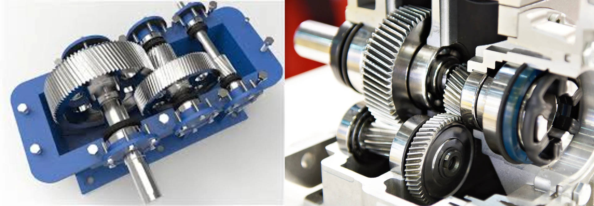
We also supply fully assembled helical gearbox units for applications where a complete parallel-shaft reducer is preferred over loose gears. Contact Korea Ever-Power with your shaft angle, speed ratio, torque, and space envelope — we will identify the most appropriate gear type and supply configuration for your specific requirement.
Maintenance and Lubrication for Crossed Helical Gears

Because crossed helical gears operate under continuous flank sliding, maintenance is more critical than for parallel helical gear arrangements. The following procedures are recommended for reliable long-term operation:
- Installation and run-in: Fix and position gears to drawing tolerances before running under load. Run in for at least 10–40 hours at no load and gradually increasing load steps to allow the contact point to polish and stabilize. Drain and replace the lubricant after the run-in period to remove wear debris.
- Lubrication management: Check lubricant level and condition every 500–1,000 operating hours. Use EP or hypoid gear oil as specified — standard mineral gear oil without EP additives accelerates surface scuffing on crossed helical gear flanks. Replace at first sign of discoloration, metallic particles, or viscosity degradation.
- Load management: Avoid shock loads and abrupt start-stop cycles. Smooth load application extends gear life significantly because the point contact area is sensitive to impact loads that would be distributed over a wider area in line-contact gear pairs.
- Temperature monitoring: Crossed helical gear drives typically run warmer than parallel helical gear drives at equivalent loads due to the sliding friction. If operating temperature consistently exceeds 80°C at the gear housing, review lubricant viscosity grade, load conditions, and cooling arrangements before tooth flank damage occurs.
- Protective covers: For open crossed helical gear drives, install a housing cover to prevent dust and contamination from entering the tooth contact zone and acting as an abrasive at the sliding contact point.
Frequently Asked Questions
What is the maximum shaft angle a crossed helical gear can accommodate?
Theoretically, shaft angles from near 0° to 90° are achievable depending on the combination of helix angles chosen for the two gears. A 90° shaft angle is achieved when both gears have 45° helix angles with the same hand, which is the most common configuration. Other angles require asymmetric helix angle distributions. Shaft angles below 20° give diminishing returns compared to a parallel helical gear arrangement, while angles above 90° are geometrically possible but rarely practical.
Why do crossed helical gears require special lubrication?
The continuous sliding motion between the tooth flanks generates more heat and stress on the oil film than rolling contact does. Standard gear oil without EP additives cannot maintain a protective film under these conditions, leading to adhesive wear (scuffing) of the contact surfaces. EP or hypoid gear oils contain sulfur-phosphorus additive packages that react with the steel surface under high local pressure and temperature to form a protective boundary layer, preventing metal-to-metal contact even when the oil film temporarily breaks down.
Can crossed helical gears transmit the same torque as parallel helical gears of the same size?
No. The point contact constraint in crossed helical gears limits the permissible Hertzian contact stress to a much smaller area than the line contact of parallel helical gears. As a rough guide, a crossed helical gear pair transmits approximately 10–30% of the torque that a parallel helical gear pair of the same module and material can handle at the same safety factor. If your torque requirement approaches the full capacity of the gear size, specify a parallel axis configuration instead.
Can Korea Ever-Power manufacture crossed helical gears not shown on the website?
Yes. All gears on the website are pre-designed templates that are manufactured to order. Custom modules, non-standard helix angles for specific shaft crossing requirements, and special bore configurations are all producible. Send drawings, specifications, or even sample gears for reverse engineering. Korea Ever-Power can also manufacture metric gears to any metric module size using in-house tooling.
How do I identify the correct replacement if I cannot read the specification from a worn gear?
Send the worn gear to Korea Ever-Power. We specialize in reverse engineering damaged or worn gears — measurement of tooth pitch, outside diameter, face width, bore, and helix angle is performed in-house and a matching replacement is manufactured from the measurement data. This service applies to crossed helical gears, parallel helical gears, spur gears, and bevel gears.
What is the typical lead time and how does Korea Ever-Power achieve fast delivery without stock?
Standard lead time is 20 business days for samples and 25 days for bulk orders. Korea Ever-Power maintains a large inventory of raw material stock, semi-finished blanks, and cutting tools. The manufacturing process for each order starts immediately from available in-house stock rather than waiting for material procurement, which keeps lead times predictable. For urgent replacement orders, expedited scheduling is available — contact us with your required delivery date.
Customer Reviews
Kim Dong-wook, Drive System Engineer, Daejeon Machine Tool Company (Q3 2024)
"We needed crossed helical screw gears for an auxiliary coolant pump drive where the shaft axes are at 70°. Sent our drawing with the required crossing angle, and Korea Ever-Power confirmed the helix angle combination needed to achieve it. Parts arrived in 23 business days. The gear pair runs smoothly with the hypoid oil we specified. No unusual noise or heat after 1,200 operating hours."
Sato Kenji, Technical Purchasing, Osaka Small Engine OEM (Q4 2024)
"Replaced the OEM crossed helical gears in a small IC engine camshaft drive. Korea Ever-Power matched our original part exactly — correct helix angle, bore, and face width — from the worn sample we sent. New parts installed without any modification. The valve train is noticeably quieter at idle compared to the worn set. Lead time was 21 days."
Park Jae-in, Elevator Service Engineer, Seoul Vertical Transport Co. (Q2 2024)
"We maintain elevator speed governor mechanisms across a portfolio of older buildings. The OEM crossed helical gear sets for the governor drive have been out of stock for years. Korea Ever-Power reverse-engineered the gear from our sample and supplied matching replacements. Fit was exact on all four units we tested. The new gears are running well after six months of normal governor operation."
Nguyen Van Minh, R&D Engineer, Ho Chi Minh City Automation Systems (Q1 2025)
"Our product uses M1.5 brass crossed helical gears for a miniature positioning mechanism where the two shafts are at 45°. We ordered prototypes first — five pieces — to validate the design before committing to a production run. Prototypes came in 19 business days and the fit in our housing was correct. The brass material also gave us the low noise we needed for an office environment product. Production order placed."
Oh Seung-hyun, Mechanical Designer, Gyeonggi CNC Systems (Q3 2024)
"Asked Korea Ever-Power to supply crossed helical screw gears in stainless steel for a food-processing machine auxiliary drive where the standard zinc-plated surface would not meet hygiene requirements. They confirmed stainless 303 was the correct grade for our application, quoted promptly, and delivered within 24 business days. No corrosion after three months of daily wash-down cleaning."
Related products
-

Industrial Alloy Steel Double Helical Gears — Full-Grade Custom Alloy Matrix for Precision Herringbone Assembly
-

Medical Double Helical Gear — Metal Grade Fine-Pitch Herringbone Gears for Diagnostic and Military Precision Drives
-

Beverage Packing Machinery Helical Gear — AGMA Class 8 for Ultra-Quiet High-Speed Packaging Drive
-

Soft Tooth Flank Helical Gear — DIN Class 6 for Rolling Mill Auxiliary Drives
-

Mining Machinery Carburized Helical Gear — 18CrNiMo6 Forged, DIN Class 6 for High-Impact Industrial Drives
-

Parallel Axis Helical Gears — High-Speed Heavy-Load Transmission for Parallel Shaft Systems
-
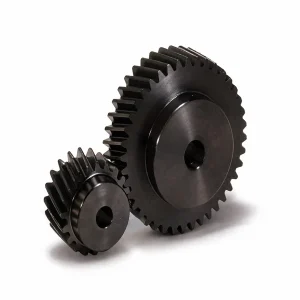
Ground Helical Gears — Precision-Ground 15° and 19°31′ for Smooth, High-Load Transmission
-

Double Helical Gear — Zero Axial Thrust for High-Torque Parallel Shaft Drives


























