
What Is a Helical Gear? — Direct Definition
A helical gear is a cylindrical gear in which the teeth are cut at an angle — called the helix angle (β) — to the axis of rotation. When a helical gear rotates and its teeth engage with a mating gear, contact begins at one end of the tooth and sweeps progressively across the face to the other end. This progressive, diagonal engagement is what distinguishes a helical gear from a spur gear, and is the mechanical cause of its quieter operation, higher load capacity, and wider speed range.
The helix angle can range from a few degrees to 45°. Higher angles mean smoother engagement, more simultaneous tooth contact, and lower noise — but also higher axial thrust on the shaft bearings. At β = 0°, the tooth is parallel to the shaft axis and the gear is a spur gear. Korea Ever-Power manufactures helical cut gears at helix angles from 5° to 45°, in all standard industrial alloy steel and stainless grades.

Construction of a Helical Gear — Parts and Key Geometry
It has the same fundamental geometric elements as a spur gear, with one important addition — the helix angle that tilts the teeth. Every parameter below must be correctly specified when ordering a replacement or new helical gear:

| Part / Parameter | Definition | Typical Value / Range |
|---|---|---|
| Helix Angle (β) | The angle between the tooth trace and the shaft axis — the defining parameter of a helical gear | 5° to 45°; 15–25° most common in industrial gearboxes |
| Normal Module (Mn) | Tooth size measured perpendicular to the tooth trace — goes on the drawing; matches the cutter | M1 to M50 for industrial applications |
| Pitch Diameter (d) | The reference circle diameter: d = Mn × z / cos β — note the cos β term that differs from a spur gear | 20 mm to 2500 mm |
| Face Width (b) | Axial length of the tooth — controls torque capacity and overlap contact ratio | Typically 6–15 × Mn for industrial drives |
| Pressure Angle (α_n) | Tooth profile shape angle measured in the normal plane | 20° is the universal standard; 14.5° and 25° also used |
| Addendum / Dedendum | Tooth height above and below the pitch circle — standard values follow from the module | Addendum = 1 × Mn; Dedendum = 1.25 × Mn (standard) |
| Accuracy Class (DIN) | Tooth profile and lead tolerance grade: Class 3 is tightest, Class 9 is loosest | Class 3–6 requires tooth grinding; Class 7–9 achieved by hobbing |
How a Helical Gear Differs from a Spur Gear

The contact line in a spur gear is parallel to the shaft axis and appears instantaneously — in a helical gear it is diagonal and sweeps progressively. This is the mechanical source of all the differences listed below
The only geometric difference between a spur gear and a helical gear is the helix angle. But that angle changes the engagement mechanics fundamentally:
Noise — 8 to 12 dB(A) Quieter
The spur gear’s instantaneous contact creates a force impulse at every tooth pitch — the source of the characteristic high-pitched gear whine. The helical gear’s diagonal sweep distributes force entry over time, reducing excitation amplitude at mesh frequency by 8–12 dB(A). On the perceived loudness scale, 10 dB means roughly half as loud.
Load Capacity — 25 to 50% Higher
A helical gear has a total contact ratio of 2.0–4.5 versus 1.2–1.6 for a spur gear. More tooth pairs in simultaneous contact means each pair carries a smaller fraction of the total force — reducing peak tooth root stress by 25–40% and allowing 25–50% more total torque in the same gear diameter and material grade.
Speed Range — 10× Higher Maximum
Spur gears become impractical above ~15 m/s pitch-line velocity due to dynamic overload from repeated tooth entry impact. Ground helical gears operate reliably to 150 m/s — covering everything from slow industrial drives to high-speed turbine gearboxes in a single gear family.
Axial Thrust — the Trade-Off
The oblique tooth creates a force component along the shaft axis: F_a = F_t × tan β. A spur gear generates zero axial thrust. This is the only genuine disadvantage of a helical gear, managed with angular-contact bearings or eliminated entirely with a double helical (herringbone) configuration.
Types of Helical Gears — The Four Main Configurations

The four types of helical gear — each serves a different shaft geometry and application requirement
The term “helical gear” covers four distinct configurations. Choosing the wrong type is a common design error — it must be corrected at the layout stage, not at the detail design stage.
Single Helical Gear
Standard helical gear for parallel-shaft drives. Generates axial thrust reacted by bearings. Covers M1 instruments to M50 mill pinions — 80%+ of all enclosed gearbox applications.
Double Helical (Herringbone)
Two opposing helix sections on one body — axial forces cancel, zero net shaft thrust. Ball mills, marine main drives, offshore winch reducers. See double helical gear for design detail.
Crossed Helical (Screw Gear)
Non-parallel, non-intersecting shafts at any angle. Point contact limits load capacity to light-duty instrument drives, camshaft drives, and positioning actuators.
Helical Rack and Pinion
Rotational to linear motion. Quieter and lower dynamic load than straight racks. CNC machine tool axes, EV steering columns, automated warehouse cranes.
Where Are Helical Gears Used? — Key Applications
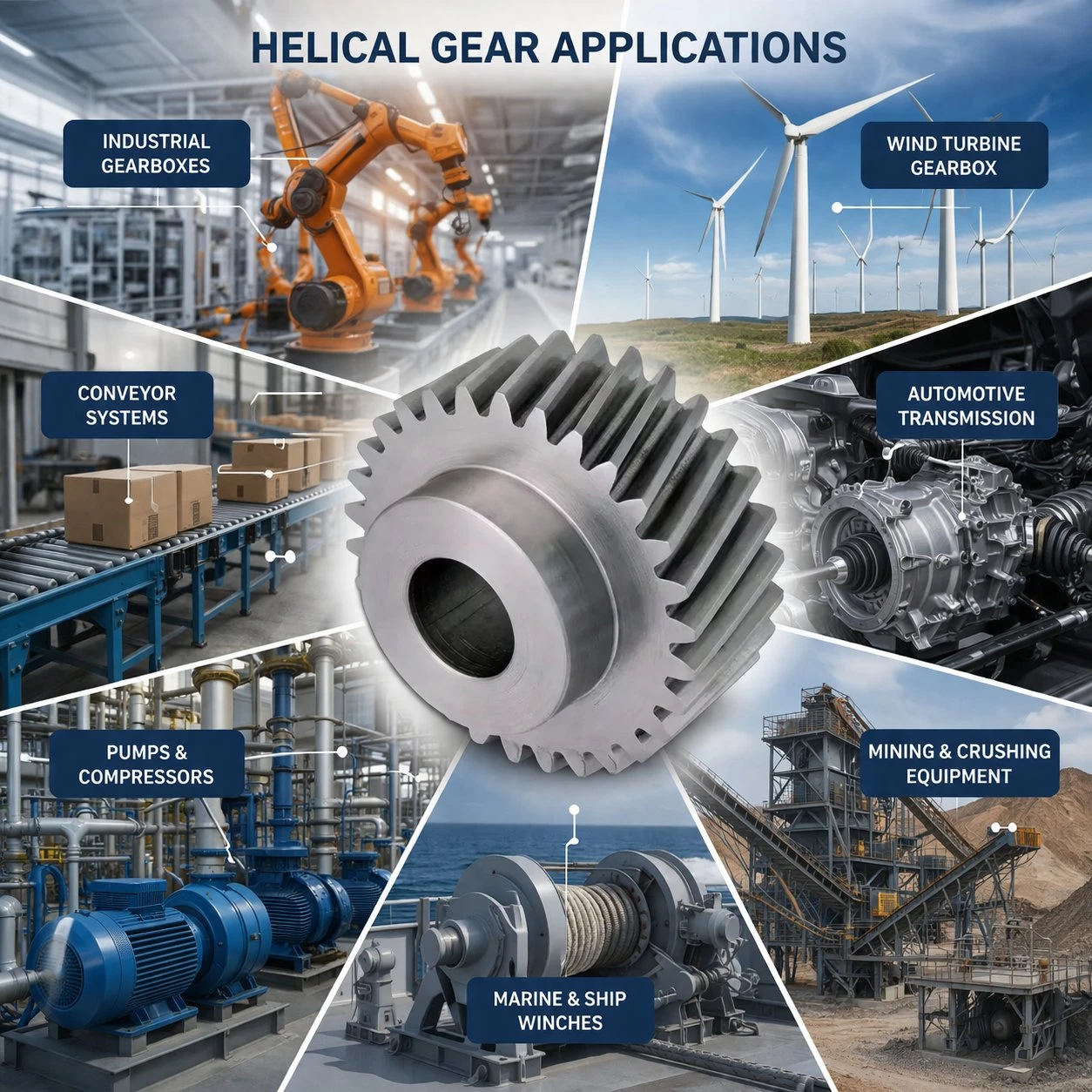
Helical gears appear wherever noise control, high torque density, and reliability matter simultaneously — automotive, industrial machinery, CNC machine tools, marine and railway
Helical gears are used in virtually every enclosed power transmission application above 10 m/s pitch-line velocity or where noise is a design constraint. The most significant application sectors:
- Automotive transmissions — all modern manual and automatic transmissions use helical gears exclusively; NVH cabin noise requirements make spur gears impractical
- Electric vehicle (EV) single-speed reducers — without engine noise masking, any mesh frequency tone appears directly in the cabin; ground helical gears at DIN Class 4–5 are the standard specification
- Industrial helical gearboxes — crane hoists, centrifugal compressor reducers, conveyor drives; the combination of torque density and smooth power delivery makes helical the default for enclosed drives above 50 kW
- CNC machine tools — spindle gearboxes and feed-axis reducers; transmission error appears directly as surface roughness on machined parts, making DIN Class 5–6 ground helical gears the standard specification
- Marine and railway — main propulsion gearboxes, traction gearboxes; high speed and strict noise limits are met by ground helical gears at DIN Class 4–6
Korea Ever-Power manufactures helical gears for all these sectors from its Korean facility, with HÖFLER grinding capability to DIN Class 3 and material documentation to classification society standards (DNV, Lloyd’s, ABS, KR). As a direct helical gear manufacturer, Korea Ever-Power supplies single-piece prototypes and scheduled production runs with full material and dimensional documentation. For high-ratio 90° reduction in the same industrial applications, the worm gear range provides the compact right-angle alternative.
What Materials Are Helical Gears Made From?
The material grade for a helical gear is determined by the application’s torque, speed, duty cycle, environment, and life requirement. The most common material grades in industrial use:
| Material Grade | Heat Treatment | Application |
|---|---|---|
| 45# Carbon Steel | QT, HB 220–280 | Moderate-duty conveyors, agitators — lowest cost |
| 42CrMo (AISI 4140) | Induction HRC 50–55 | Rolling mills, mining, shock-loaded drives |
| 20CrMnTi (≈20MnCr5) | Carburized HRC 58–62 | Automotive, CNC machine tools, high-cycle drives |
| 17CrNiMo6 / 18CrNiMo6 | Carburized HRC 58–62 | Railway traction, marine, offshore, sub-zero environments |
| SS304 / SS316L | Solution treated | Food processing, pharmaceutical, marine wash-down |
| POM / PA / PEEK | — | Light-duty instruments, medical devices, no-lubrication drives |
Frequently Asked Questions About Helical Gears
What does “helical” mean in a helical gear?
“Helical” refers to the helical (spiral) path traced by the tooth as it wraps around the gear cylinder. Helix comes from the Greek word for spiral. In a helical gear, the tooth follows this helical path rather than running straight (parallel to the axis) as in a spur gear. The angle at which the helix is inclined relative to the shaft axis is the helix angle β.
Are all gearboxes made with helical gears?
No, but most enclosed industrial gearboxes above 10 m/s pitch-line velocity do use helical gears. Spur gears are still used in low-speed open drives, agricultural machinery, and simple positioning mechanisms. Bevel gears (with intersecting 90° shafts) and worm gears (non-parallel, high-ratio) are used where the shaft arrangement cannot be served by helical gears. Within the parallel-shaft cylindrical gear category, helical gears dominate for any application where noise, speed, or torque density matters.
How long do helical gears last?
Correctly specified and lubricated gears of this type in enclosed gearboxes typically achieve service lives of 20,000–50,000 hours before the first maintenance action. Carburized, ground helical cut gears in automotive transmissions are designed for vehicle lifetime (300,000+ km). The main failure modes are pitting (contact fatigue), tooth root bending fatigue, and scuffing — all of which are controlled by correct material and accuracy class specification, adequate lubrication, and keeping operating conditions within the design envelope.
What is the difference between a helical gear and a worm gear?
This gear type transmits between parallel shafts with line contact — high efficiency (98–99.5%) and high torque capacity. A worm gear transmits between non-parallel, non-intersecting shafts (typically 90°) via sliding contact — lower efficiency (50–90% depending on lead angle) but very compact, high single-stage reduction ratios (5:1 to 100:1), and self-locking capability. They serve different shaft geometries and are not interchangeable. See the complete worm gear range for applications requiring 90° high-ratio compact reduction.
What accuracy class should I specify for a replacement helical gear?
Match the accuracy class of the original gear where possible. For standard industrial gearboxes (crane, conveyor, compressor) up to 20 m/s: DIN Class 7–8, precision hobbing. For automotive, CNC machine tool, or railway applications: DIN Class 5–6, tooth grinding required. If the original gear was ground (you can tell from the Ra ≤ 0.8 µm tooth flank surface appearance vs the rougher as-hobbed finish), specify grinding for the replacement. If unsure, send the worn gear to Korea Ever-Power — the team measures all parameters and can confirm the original accuracy class from the tooth flank surface condition.
When to Choose a Helical Gear — and When to Consider Alternatives
Selecting the right gear type requires confirming that the shaft arrangement, load profile, and noise requirements all point to a cylindrical parallel-shaft drive. A helical gear is appropriate when:
- Both shafts are parallel — the fundamental requirement for a cylindrical gear of any type. Intersecting shafts require bevel gears; non-parallel, non-intersecting shafts require worm gears or crossed helical gears.
- The pitch-line velocity exceeds 8–10 m/s, or noise is a design constraint at any speed. Below this threshold, a spur gear is simpler and cheaper. Above it, the progressive tooth engagement of a helical gear is the only practical path to controlled noise and dynamic load.
- Maximum torque in a constrained space — the load-sharing advantage of the helical tooth form delivers 25–50% more torque in the same gear diameter and material, without any other design change.
- Service life is a priority — ground gears of this type achieve 3–5× longer pitting life than as-hobbed spur gears at equal operating conditions, primarily due to better EHL film formation at Ra ≤ 0.6 µm tooth flank surfaces.
Where axial thrust genuinely cannot be accommodated — for instance, in drives where very long unsupported shafts preclude thrust bearings, or where the housing layout makes axial load management impractical — the double helical (herringbone) configuration addresses the problem at the gear level. The two opposing helix sections cancel thrust internally, so the shaft and bearings experience zero net axial force regardless of how large the helix angle is. This makes the herringbone form the standard for high-power continuous drives like ball mill main gearboxes and marine propulsion reducers.
For 90° shaft arrangements, a bevel gear is the correct solution rather than a crossed helical form — the crossed configuration has point contact that limits load capacity to instrument-level duty. For high single-stage reduction ratios (5:1 to 100:1) at 90°, a worm gear provides the compact solution that a cylindrical gear form cannot match.
Korea Ever-Power — Precision Helical Gear Manufacturer

CMM dimensional verification and gear analyser measurement — Korea Ever-Power provides full inspection documentation with every helical gear order as standard
Korea Ever-Power is a direct helical gear manufacturer based in Korea, with in-house capability from forging through HÖFLER gear grinding. MOQ 1 piece for prototypes and maintenance replacements. ISO 9001:2015 certified. Standard documentation with every order: material certificate, gear analyser report (profile, lead, pitch per DIN 3962), 100% MPI on ground surfaces, and CMM dimensional report.
Have a Question About Helical Gears?
Whether you need a new gear designed, a replacement specified, or simply an answer to a technical question — Korea Ever-Power’s engineering team responds within 24 working hours.
MOQ 1 piece · Material cert + gear analyser report · DIN Class 3–9 · M1 to M50
Editor: Cxm


























