
Helical Cut Gears vs Straight Cut Gears — The Short Answer
Helical cut gears outperform straight cut gears on every performance metric that matters at moderate-to-high speeds: they are 8–12 dB(A) quieter, transmit 25–50% more torque in the same gear diameter, and operate reliably at pitch-line velocities up to 150 m/s versus roughly 10–15 m/s practical for straight cut gears. The single trade-off is an axial thrust force generated by the oblique tooth — manageable with standard angular-contact bearings, or cancelled entirely by a double helical (herringbone) configuration.
Straight cut (spur) gears are simpler and cheaper to manufacture, generate no axial thrust, and remain the right choice for low-speed auxiliary drives, open gearing, and compact mechanisms where noise is not a design constraint. The comparison below covers every dimension that matters when selecting between the two.
Tooth Engagement — The Root Cause of All Performance Differences
Every difference between helical cut gears and straight cut gears ultimately traces back to a single geometric fact: how the tooth enters and exits the mesh zone.

The contact line tells the whole story — instantaneous and parallel to the shaft axis in a straight cut gear; diagonal and progressive in a helical cut gear
How Straight Cut Gears Engage
In a straight cut (spur) gear, the tooth face is parallel to the shaft axis. The instant a tooth pair enters the mesh zone, contact appears simultaneously across the full face width. The transmitted force jumps from zero to its maximum value in a fraction of a millisecond, then drops back to zero as the tooth exits. This force impulse repeats at every tooth pitch — typically 300–3000 Hz — generating the characteristic high-pitched whine of straight cut gears at speed, and creating a dynamic overload on the tooth root that limits both fatigue life and maximum operating speed.
How Helical Cut Gears Engage
In a helical cut gear, the tooth is inclined at helix angle β. A new tooth pair begins contact at a single point on the leading edge. The contact zone grows, sweeps diagonally across the full face width, then shrinks and exits at the trailing edge. The force entry is gradual, the peak load is distributed across multiple simultaneously contacting tooth pairs, and the exit is equally smooth. The result: no force impulse, no mesh-frequency excitation spike, no dynamic overload. The physics of progressive engagement is the direct mechanism behind every quantitative advantage that helical cut gears hold over straight cut gears.
Full Engineering Comparison — Helical Cut Gears vs Straight Cut Gears
The table below quantifies the performance difference across all dimensions that matter to a gearbox designer or procurement engineer. Korea Ever-Power’s helical cut gears are produced to ground DIN Class 3–9 in the full range of alloy steel and stainless grades.
| Performance Dimension | Straight Cut (Spur) Gear | Helical Cut Gear |
|---|---|---|
| Tooth engagement | Instantaneous — full face width, parallel contact line | Progressive — diagonal sweep from one edge to the other |
| Total contact ratio ε_γ | 1.2–1.6 (transverse only; no overlap component) | 2.0–4.5 (transverse + overlap; scales with β and face width) |
| Simultaneous tooth pairs | 1–2 pairs, alternating | 2–5 pairs, continuously distributed |
| Operating noise level | High — strong mesh-frequency tone; 78–85 dB(A) typical at 1500 RPM | 8–12 dB(A) lower at identical speed and load conditions |
| Torque capacity (equal size) | Baseline | +25 to +50% due to multi-pair load sharing |
| Dynamic load factor K_v | 1.3–1.8 at moderate speed | 1.05–1.2 (ground); lower peak tooth root stress |
| Max pitch-line velocity | ~10–15 m/s practical limit for noise-sensitive applications | Up to 150 m/s (ground, DIN Class 3–4) |
| Axial force | Zero — no axial thrust generated | F_a = F_t × tan β; managed by bearings or double helical config |
| Mesh efficiency | 97–98% | 98–99.5% (ground variants); better EHL film formation |
| Tooth root bending fatigue | Higher peak stress — fewer pairs sharing load | 25–40% lower peak stress at equal transmitted torque |
| Contact fatigue (pitting) | Baseline — limited by EHL film at moderate speed | 3–5× longer pitting life in ground variants (Ra ≤ 0.6 µm) |
| Manufacturing complexity | Lower — simpler hobbing setup, no axial lead programming | Slightly higher — helix angle must be controlled throughout grinding |
| Gear diameter (equal Mn, z) | d = Mn × z | d = Mn × z / cos β — slightly larger at same Mn and z |
| Relative cost (standard grade) | Baseline | ~8–15% higher; gap narrows as precision requirements rise |
Noise and Vibration — Why the Gap Is So Large
The 8–12 dB(A) noise advantage of helical cut gears over straight cut gears is not marginal — on the A-weighted decibel scale used for occupational and automotive noise measurement, 10 dB is roughly perceived as halving loudness. Understanding why the gap is this large clarifies when investing in helical gears is non-negotiable versus when straight cut gears are acceptable.

The Mechanism of Straight Cut Gear Noise
Gear noise is dominated by transmission error — the deviation from perfectly uniform rotation at the gear mesh. In a straight cut gear, each tooth pair entering contact produces a step in the transmitted force. This step excites vibration in the gear body, shafts, and housing at the mesh frequency (f_z = n × z / 60, where n is RPM and z is tooth count) and its harmonics. At 1500 RPM with 20 teeth, mesh frequency is 500 Hz — in the range of peak human hearing sensitivity. The impulsive excitation at this frequency is intrinsically high in straight cut gears, regardless of how precisely the tooth profile is cut.
Why Helical Cut Gears Are Quieter
In a helical cut gear, the diagonal contact line means that the force entry is spread over the time it takes the contact zone to sweep across the face width. The step in transmitted force is replaced by a smooth ramp. The excitation amplitude at mesh frequency drops dramatically — by 8–12 dB(A) at β = 20–25°. Ground helical cut gears at DIN Class 5 reduce transmission error amplitude a further 60–80% compared with hobbed gears of the same module, because profile and lead deviations that cause additional force variation are eliminated. The combined result: a ground helical gear at DIN Class 5 can run 15–18 dB(A) quieter than an as-hobbed straight cut gear in the same application.
Load Capacity and Fatigue Life — The Quantitative Difference
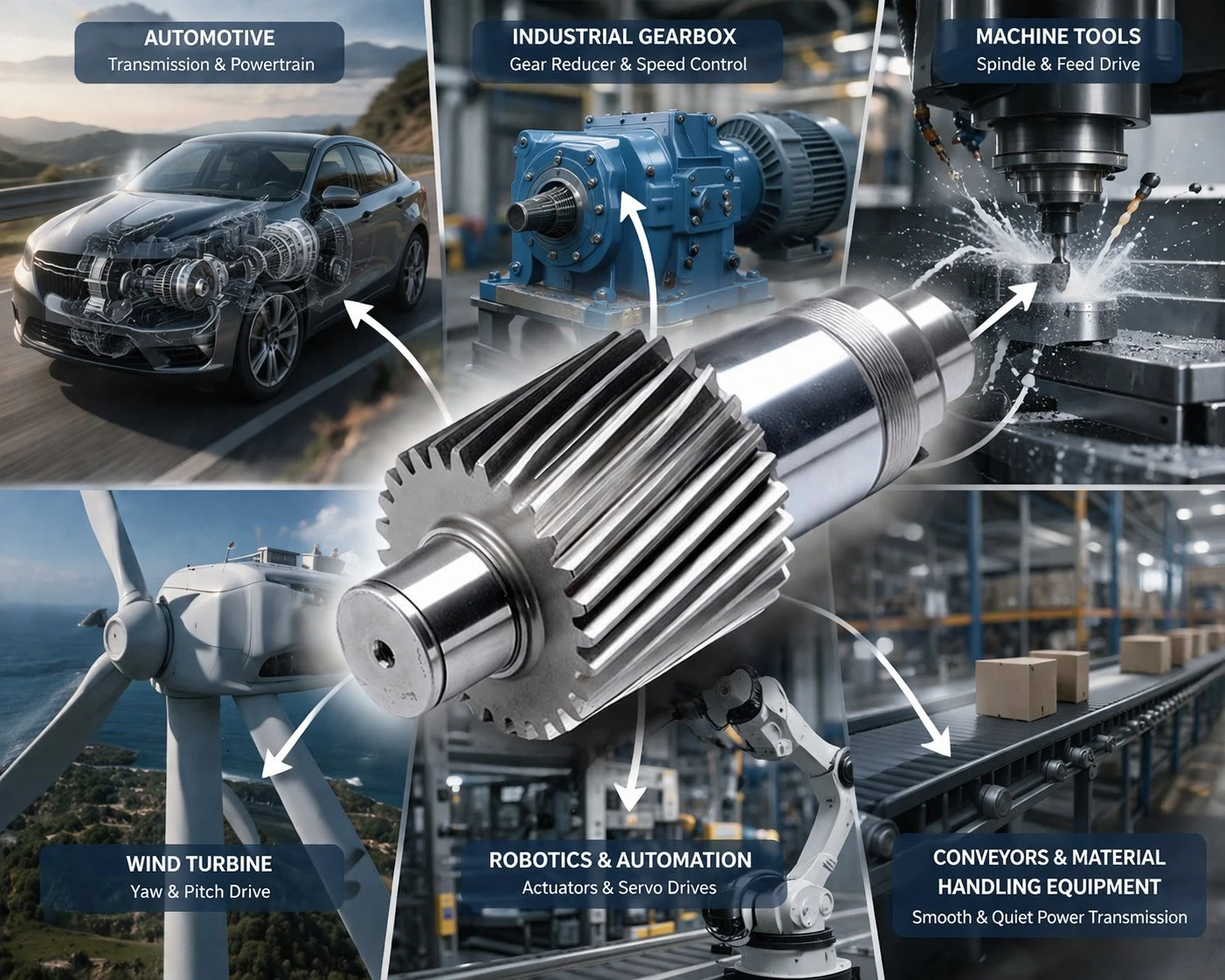
Heavy industrial drives — crane hoists, centrifugal compressors, rolling mill pinion stands — specify helical gears because they transmit 25–50% more torque in the same gear envelope
Tooth Root Bending Stress
ISO 6336 tooth root bending strength calculation uses a load distribution factor K_F that accounts for how many tooth pairs simultaneously share the load. In a straight cut gear with contact ratio 1.5, the average number of simultaneous pairs is 1.5 — but the peak load is still carried by a single pair for part of each cycle. In a helical cut gear with total contact ratio 2.8, the load is never concentrated on a single pair — it is always distributed across 2–3 pairs. The peak bending stress at the tooth root is reduced by 25–40% for the same transmitted torque, directly extending bending fatigue life.
Contact Fatigue (Pitting) and EHL Film
At the tooth contact zone, the key factor for pitting resistance is the specific film thickness λ = h_min / Ra_combined. A ground helical cut gear at Ra ≤ 0.6 µm achieves λ > 2.0 (full EHL film) at pitch-line velocities above 5 m/s with standard mineral gear oil — metal-to-metal contact is avoided and pitting initiation is suppressed. An as-hobbed straight cut gear at Ra ≈ 3.2 µm typically has λ < 1.0 at the same conditions, operating in the mixed-lubrication regime where pitting initiates progressively. This surface condition difference, combined with the lower peak contact pressure of helical gears (due to the longer contact line), produces the 3–5× pitting life advantage observed in practice between ground helical and as-hobbed straight cut gears under equivalent load and speed.
When to Choose Helical Cut Gears — and When Straight Cut Is Adequate
Choose Helical Cut Gears When:
- Pitch-line velocity exceeds 8–10 m/s
- Noise or vibration is a design constraint (automotive, CNC, medical, packaging)
- Maximum torque density is required in a constrained envelope
- Long service life is critical and gear replacement is expensive or disruptive
- High-speed turbine gearboxes, compressor drives, railway traction
Straight Cut Gears Remain Appropriate When:
- Pitch-line velocity is below 5–8 m/s and noise is not a concern
- Shaft bearing arrangement cannot accommodate any axial thrust
- Very wide gears where manufacturing a consistent helix across the face is impractical
- Low-cost auxiliary drives where gear replacement is frequent and cost dominates
- Open gearing in agricultural, slow-speed conveyor, and simple positioning mechanisms
Manufacturing Process Differences That Affect Selection
From a procurement perspective, the manufacturing differences between helical cut gears and straight cut gears are modest in process but significant in outcome. A straight cut gear is hobbed with the hob axis tilted only by the lead angle of the hob itself. A helical cut gear requires the hob axis to be tilted by the helix angle plus the hob lead angle, and the gear blank must rotate at a precisely controlled differential rate as it traverses — a more complex but entirely standard CNC gear hobbing operation.
The larger practical difference is in heat treatment and finishing. Carburized straight cut gears can often be used as-hobbed after heat treatment at DIN Class 7–9 because the profile distortion is primarily in the tooth height direction and does not dramatically change the pitch-line engagement character. Carburized helical cut gears require tooth grinding after heat treatment to achieve DIN Class 4–6 because helix angle and lead accuracy degrade with distortion — and helix angle error produces edge loading across the face width, which directly causes premature fatigue at the tooth edges.
Korea Ever-Power — Precision Helical Cut Gear Manufacturer

In-house quality control at Korea Ever-Power — every helical cut gear is verified against the drawing before shipment
Korea Ever-Power manufactures precision helical cut gears entirely in-house — from forging blank through gear hobbing, carburizing, and tooth grinding — as a direct gear manufacturer in Korea. The manufacturing range covers M1 to M50, OD 20 mm to 2500 mm, in alloy steel (45# through 17CrNiMo6), stainless (SS304/SS316), and engineering plastic grades. As a helical cut gear supplier with direct engineering consultation, Korea Ever-Power provides specification recommendations as part of the quotation process — not just a price per piece.
For applications where axial thrust cannot be accepted at any level, the double helical (herringbone) configuration eliminates thrust entirely. Detailed design resources are available at double helical gear. For compact high-ratio right-angle drives in the same machinery, the worm gear range covers self-locking auxiliary configurations.
Frequently Asked Questions
Can helical cut gears directly replace straight cut gears in the same gearbox?
Not without design changes. The pitch diameter formula differs: a helical cut gear with the same normal module and tooth count has d = Mn × z / cos β, whereas a straight cut gear has d = Mn × z. The centre distance changes, so the mating gear and shaft positions must be redesigned. Additionally, the housing and bearing arrangement must accommodate the axial thrust generated by the helical tooth. A direct drop-in replacement at identical centre distance requires the helix angle to be calculated backward from the existing centre distance, which is possible but not trivial.
At what speed does it become essential to switch from straight cut to helical cut gears?
There is no hard boundary, but as a practical guideline: above 8–10 m/s pitch-line velocity, straight cut gear noise and dynamic overload become problematic in most enclosed gearboxes. Above 15 m/s, straight cut gears are impractical for noise-sensitive applications. Above 25 m/s, helical cut gears are essentially universal. For any application where noise or vibration is a design requirement at any speed — automotive, medical, food packaging, CNC machine tools — helical cut gears are specified from the outset regardless of pitch-line velocity.
Why do helical cut gears have higher mesh efficiency than straight cut gears?
Two mechanisms. First, the progressive engagement of helical cut gears reduces the dynamic load factor K_v — lower peak loads mean lower instantaneous frictional losses at the contact zone. Second, ground helical cut gears (Ra ≤ 0.6 µm) maintain a more robust EHL oil film at the contact than as-hobbed straight cut gears (Ra ≈ 3.2 µm), reducing friction in the mixed-lubrication regime that causes the majority of gear mesh losses. The combined effect is 98–99.5% mesh efficiency for precision-ground helical cut gears versus 97–98% for typical straight cut gears under the same operating conditions.
What is the difference between a helical cut gear and a double helical gear?
A standard single helical cut gear has teeth on one helix direction and generates an axial thrust that must be reacted by bearings. A double helical gear has two opposing helix sections on the same gear body — the axial forces from both halves cancel internally, resulting in zero net axial thrust at the shaft. The double helical configuration allows very large helix angles (30–45°) for maximum contact ratio and noise reduction without requiring thrust-capable bearings.
Is the 25–50% torque capacity advantage of helical cut gears achieved without any size increase?
Yes, the torque increase is achieved in the same gear envelope (same outer diameter and face width), using the same material grade and heat treatment. It comes from the higher contact ratio: multiple tooth pairs sharing the load simultaneously reduce the peak stress at each tooth, allowing more total torque before fatigue limits are reached. The gear is physically the same size — the extra torque capacity comes from better load distribution geometry, not larger material cross-section.
Compare Specifications for Your Drive Application
Send your current straight cut or helical gear drawing — or just the operating parameters — and Korea Ever-Power’s engineering team will recommend the optimum gear type, material grade, and accuracy class for your specific application.
MOQ 1 piece · Material cert + gear analyser report standard · M1 to M50 · DIN Class 3–9
Editor: Cxm


























