
Forged vs Cast Helical Gears: The Engineering Guide to Metallurgical Selection
Analyze the microstructural behavior of plastically deformed steel versus solidified molten alloys. Evaluate continuous grain flow alignment, internal porosity limitations, and cyclic yield strength parameters to specify the absolute optimal gear blank manufacturing method for high-torque industrial parallel-axis drivetrains.
Metallurgical Architecture and Heavy Drivetrain Integrity
When designing continuous-duty power transmission units for heavy industrial infrastructure, mechanical engineers must look far beyond macro-geometry variables such as the module, pressure angle, and diametral pitch. The true operational ceiling of any high-speed gearbox relies entirely on the microstructural integrity of the gear blank itself. The continuous industrial debate regarding forged vs cast helical gears centers strictly on how the atomic lattice of the metal is established long before the involute teeth are ever machined. The thermodynamic origin of the steel substrate dictates its ultimate tensile strength, impact toughness, and resistance to high-cycle fatigue under extreme tangential loads.
A precision helical gear transfers kinetic energy through progressive, overlapping tooth contact. While this rolling engagement drastically reduces transmission error and acoustic resonance (gear whine), it simultaneously subjects the tooth root to severe cantilever bending stresses and the tooth flank to intense Hertzian contact pressure. If the underlying metallurgy contains microscopic impurities, entrapped gas voids, or unrefined crystalline structures, these internal anomalies will act as highly volatile stress concentrators. Under dynamic shock loading, microscopic fatigue cracks will nucleate at these defects and propagate rapidly through the material lattice, culminating in catastrophic gear shear and massive equipment downtime.

Consequently, specifying the correct manufacturing topology is non-negotiable. Forging involves heating a solid steel billet above its recrystallization temperature and applying immense hydraulic pressure to plastically deform it into a near-net shape. This physical compression eliminates internal voids and forcefully aligns the metallic grain structure. Casting, alternatively, requires melting iron or steel alloys into a liquid state and pouring the fluid into a patterned sand mold. Because the metal solidifies via a phase change without any external physical compression, the resulting atomic structure is dendritic and purely isotropic. Recognizing these foundational differences is the first step in engineering a reliable parallel-axis drivetrain.
Mechanical Property and Specification Matrix
Evaluating the ultimate load capacity limits of helical cut gears requires benchmarking the physical properties derived from their primary forming processes. The engineering table below contrasts standard closed-die forged low-alloy steel (such as 18CrNiMo7-6 or 42CrMo4) against premium cast steel and nodular cast iron (Ductile Iron, e.g., EN-GJS-600-3), establishing realistic mechanical expectations for drivetrain procurement managers calculating ISO 6336 gear life.
| Engineering Parameter | Forged Steel Helical Blank | Cast Iron / Steel Blank |
|---|---|---|
| Microstructural Form | Anisotropic (Directional Continuous Grain Flow) | Isotropic (Randomized Dendritic Crystals) |
| Ultimate Tensile Strength (UTS) | Exceptionally High (800 – 1200+ MPa) | Moderate to High (400 – 800 MPa) |
| Impact Toughness (Charpy V-Notch) | Superior; resists sudden kinetic shock loads | Lower; more vulnerable to brittle fracture |
| Internal Porosity Risk | Near Zero (Compression mechanically seals voids) | Moderate to High (Centerline shrinkage porosity inherent) |
| Acoustic Damping (NVH) | Low inherent material damping; transmits resonance | Excellent (Graphite nodules actively absorb kinetic frequencies) |
| Dimensional Scalability Limits | Strictly constrained by forging press tonnage limits | Virtually limitless; allows complex hollow hubs and spokes |
The Mechanics of Forged Steel: Austenitic Plastic Deformation and Grain Flow
The definitive mechanical superiority of a forged transmission component originates from a metallurgical phenomenon known as continuous grain flow. During raw steel production, an initial ingot is cast at the mill, which naturally contains dendritic structures and microscopic gas pockets from the solidification process. The closed-die forging process takes this billet, heats it heavily into its austenitic phase (typically between 1100°C to 1250°C), and submits it to thousands of tons of hydraulic or drop-hammer pressure. This extreme plastic deformation physically forces the solid, glowing steel to conform entirely to the shape of the die cavity.
As the metal flows under pressure, its internal grain boundaries elongate and align parallel to the external contour of the gear blank. When the CNC hobbing equipment eventually cuts the involute geometry into this substrate, the directional grain lines wrap fluidly around the tooth root fillet rather than terminating abruptly at the machined surface. This anisotropic reinforcement functions identically to the continuous fibers in high-strength aerospace composites; any bending stress applied by the motor torque must fight across the metallic fibers rather than splitting between them. This alignment drastically elevates the root bending fatigue endurance limit.
Simultaneously, the immense compressive tonnage mechanically welds shut any preexisting microscopic voids. This resulting high density is critical for surface durability. When the gear tooth flank is subjected to intense Hertzian contact pressure under operational load, there are no subsurface empty cavities to collapse. The absolute absence of voids prevents localized stress concentrations, thereby eliminating the primary initiation mechanism behind subsurface macro-pitting and destructive spalling.

The Mechanics of Cast Substrates: Dendritic Solidification and Internal Porosity

Evaluating the precise contrast of forged vs cast helical gears necessitates an objective understanding of foundry thermodynamics. Casting dictates that the component takes its permanent shape directly from a liquid phase. As molten steel or iron cools within an engineered sand mold, crystals nucleate at the cooler exterior boundaries and grow inward toward the thermal center. This cooling gradient results in an isotropic microstructure—meaning the mechanical yield strength is relatively uniform across all spatial axes, but it intrinsically lacks the localized peak fatigue reinforcement provided by forged flow lines.
The primary metallurgical liability associated with the casting process is volumetric contraction. Liquid steel shrinks significantly as it solidifies. If the foundry’s gating and risering systems fail to feed fresh liquid metal continuously into the thickest sections of the gear hub or rim, severe micro-shrinkage cavities will inevitably form deep within the core. If one of these microscopic voids happens to align directly with the pitch circle diameter (PCD) or the root fillet of the final machined gear, it acts as a severe stress amplifier, frequently triggering sudden fracture under normal operating loads.
However, modern cast materials have evolved substantially to mitigate inherent brittleness. Today’s engineers rarely specify standard gray cast iron. Instead, they mandate Nodular Cast Iron (Ductile Iron) or Austempered Ductile Iron (ADI). By inoculating the liquid melt with magnesium, the carbon graphite is forced to precipitate into microscopic spheres (nodules) rather than sharp, intersecting flakes. These spherical inclusions disrupt the iron matrix far less, providing excellent tensile strength. Furthermore, the embedded graphite acts as a natural vibration damper, meaning a cast ductile iron helical drivetrain will consistently generate a much lower Noise, Vibration, and Harshness (NVH) signature than a forged steel equivalent.
Machining Dynamics, Tool Wear, and Thermodynamic Heat Treatment
The physical divergence between forged vs cast helical gears becomes drastically apparent during secondary manufacturing operations, specifically CNC hobbing and case-hardening treatments. The consistency of the initial substrate directly dictates cutting tool life, surface finish, and dimensional stability.
Hobbing and Grinding Machinability: Forged steel blanks possess a completely homogeneous and predictable structure. This uniformity allows carbide hobs and CBN grinding wheels to cut smoothly, generating predictable tool wear and superior surface finishes (Ra). Conversely, cast blanks often contain silica sand inclusions baked into the near-surface layers or localized hardened chill zones caused by uneven mold cooling. Striking a microscopic ceramic sand inclusion during a high-speed hobbing pass will instantly chip or shatter an expensive cutting tool. Furthermore, if final profile grinding exposes a subsurface shrinkage void on the active tooth flank, the gear will fail rapidly in the field because the void disrupts the Elastohydrodynamic Lubrication (EHL) oil film, causing metal-to-metal scuffing.
Carburizing and Quench Distortion: Heavy-duty industrial drivetrains rely heavily on thermochemical case-hardening (such as gas carburizing) to generate extreme surface wear resistance while maintaining a ductile core. Because forged blanks possess near-perfect uniform density, carbon gas diffuses into the substrate at a highly predictable rate. When the gear is rapidly quenched in oil, the martensitic transformation occurs evenly, keeping geometric distortion to an absolute minimum. Cast gears struggle severely in this environment. Microscopic density variations and internal porosity cause erratic carbon absorption. If the quenching fluid penetrates a subsurface void near the tooth root, it creates immense localized hydrostatic pressure, frequently inducing spontaneous quench cracking or severe dimensional warping.
Dimensional Scalability and Heavy Industry Manufacturing Economics

Engineering specifications are frequently overruled by sheer physical manufacturing limitations. Producing closed-die forging tooling is an incredibly capital-intensive process. The immense NRE (Non-Recurring Engineering) die costs must be amortized over high-volume production runs. Additionally, the hydraulic tonnage required to compress a solid steel disc becomes practically unfeasible once the gear’s outer diameter (OD) exceeds 1.5 to 2.0 meters. While advanced seamless ring rolling can produce forged rim sections up to 3 meters, standard solid forgings are heavily constrained by equipment envelopes.
When machinery designs require massive transmission elements—such as 6-meter girth gears weighing over 20 tons—sand casting becomes the absolute and only standard. Foundries can utilize relatively low-cost wooden or resin patterns to mold massive, one-off components. Casting allows engineers to design complex, lightweight geometries integrating hollow bearing hubs and intricate radial spokes directly into the monolithic structure, severely reducing the rotational mass moment of inertia without requiring thousands of hours of material-removal milling on a gantry machine.
Specifying Blank Formats by Industrial Application
Mandating Forged Helical Architecture
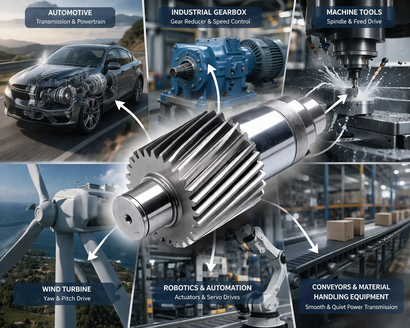
Forged alloys are the definitive engineering specification for applications demanding intense power density within a heavily constrained physical housing footprint. Automotive EV reduction drives, marine propulsion units, aerospace actuators, and high-speed turbine compressors exclusively utilize forged metallurgy to withstand instantaneous shock torque and continuous high-cycle fatigue without shearing.
Design Parameter: When designing high-impact industrial shredders that utilize a double helical gear arrangement to cancel axial thrust, specifying dense forged alloy steel is strictly required. The extreme reverse-shock torque would easily shatter a porous cast component.
Mandating Cast Helical Architecture
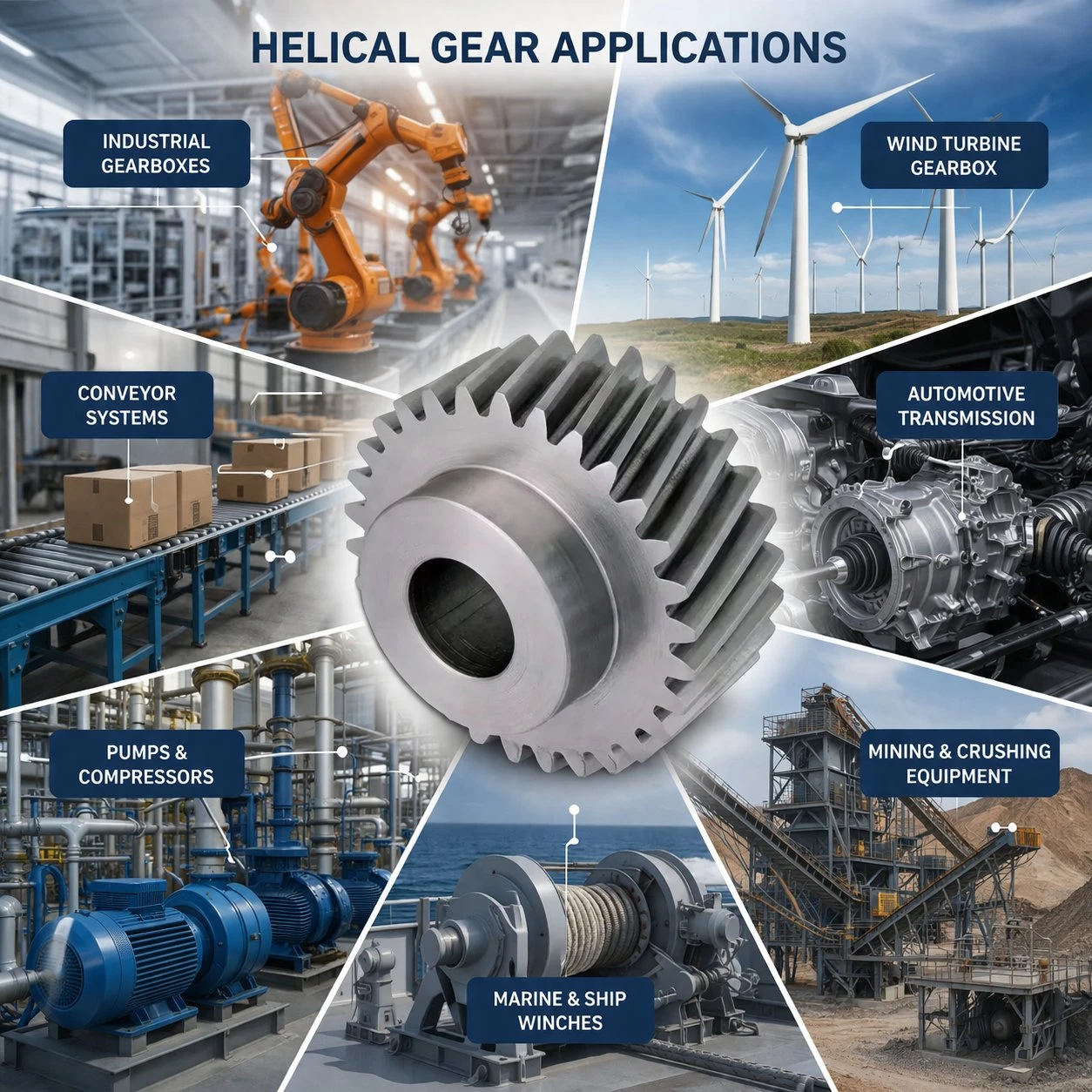
Castings overwhelmingly dominate large-scale, low-RPM industrial infrastructure where sheer physical dimensions are required to transmit continuous torque. Prominent applications include rotary cement kilns, massive ball mill girth gears, sugar mill crushers, and dragline excavator swing drives. The massive tooth module compensates for the material’s lower intrinsic fatigue limit.
Design Parameter: In extreme heavy-duty reducers requiring self-locking features and immense single-stage right-angle turns, engineers often pair a hardened forged steel pinion with a massive worm gear cast centrifugally from high-tin bronze to dissipate thermal friction and act as a sacrificial wear component.
Korea Ever-Power: Certified Metallurgical Integrity and Precision Grinding

Extracting optimal fatigue endurance from a drivetrain requires a manufacturing partner with absolute authority over both metallurgical inspection and sub-micron machining. Functioning as a premier helical gear manufacturer headquartered in South Korea, Korea Ever-Power Worm Gear Co.,Ltd executes rigorous, highly certified manufacturing workflows for heavy industrial procurement engineers across Japan, Korea, and Southeast Asia.
- Rigorous NDT Diagnostics: We subject every raw blank to ISO 9001-certified Ultrasonic Testing (UT) to detect centerline shrinkage, followed by Magnetic Particle Inspection (MPI) post-machining to certify absolute surface integrity.
- Uncompromising Grinding Precision: Leveraging our array of premium German-engineered HÖFLER profile grinding centers, we eliminate lead, profile, and pitch errors, consistently achieving DIN Class 3 to 9 accuracy grades.
- Massive Envelope Capacity: Our turning, hobbing, and grinding infrastructure is calibrated to process heavy-duty parallel components reaching up to 2500mm in Outer Diameter (OD).
- Thermodynamic Stability: We maintain strict control over atmospheric carburization and localized induction hardening cycles, optimizing the hardened case depth without degrading the substrate’s core impact toughness.
Frequently Asked Engineering Questions
Can a cast iron helical gear replace a forged steel gear directly?
Absolutely not. A direct 1:1 material substitution without recalculating the kinematics is highly dangerous. Ductile cast iron possesses a fundamentally lower yield strength and Charpy impact rating compared to forged alloy steel. Replacing a forged pinion with a casting of identical dimensions drastically reduces the gearbox’s maximum transmittable torque limit and invites catastrophic failure. To safely utilize cast iron, mechanical engineers must redesign the system, typically increasing the gear module (tooth size) or extending the face width to compensate for the lower fatigue threshold.
Why is Ultrasonic Testing (UT) exceptionally difficult on ductile cast iron?
Ultrasonic NDT relies on high-frequency sound waves propagating linearly through a uniform metallic matrix. In hot-forged steel, the densely compacted grain structure allows waves to pass easily, making internal defects highly visible on the oscilloscope. In ductile cast iron, the millions of microscopic spherical graphite nodules physically scatter and attenuate the sound waves. This acoustic “noise” heavily obscures the signal, making it incredibly challenging for NDT technicians to differentiate between normal graphite dispersion and critical structural shrinkage porosity, often requiring supplementary Radiographic Testing (X-ray).
Does the manufacturing process dictate the helix angle limits?
No. The exact mathematical generation of the helix angle is executed independently during the CNC hobbing and grinding phases. The raw blank’s origin—whether it was cast in sand or forged under a hydraulic hammer—has zero technical impact on the theoretical limits of the helix angle, the contact ratio, or the resulting transverse profile geometry. However, forged blanks allow the manufacturer to align the grain flow specifically to support the forces generated by aggressive helix angles.
What is a “seamless rolled ring forging,” and when is it specified?
For extremely large internal planetary ring gears or hollow external bull gears, specifying a solid forged disc is prohibitively expensive and heavy. Instead, engineers specify a seamless rolled ring forging. A solid steel billet is pierced to create a donut shape, then heated and rolled dynamically between immense mandrels. This process expands the diameter up to 3 meters while forcing the grain structure to flow circumferentially. This circumferential grain flow maximizes hoop strength, preventing the thin ring from fracturing under extreme radial expanding loads.
Why do some cast gear flanks experience rapid pitting failure?
Pitting is a surface fatigue phenomenon caused by intense Hertzian contact stress repeatedly compressing the tooth flank. If a cast blank harbors subsurface micro-porosity or non-metallic sand inclusions located just a few millimeters beneath the pitch line, the high localized pressure will cause that void to collapse structurally. The surface material above the void then shears away, creating a macroscopic pit that destroys the gear. Forged steel, being thoroughly compacted and 100% dense, completely eliminates this specific subsurface void failure mechanism.
Is it possible to combine both methods in a single multi-stage gearbox?
Yes, this is standard engineering practice. In a typical heavy industrial reduction drive, the high-speed input pinion is relatively small in diameter and subject to an intense frequency of cyclic loading, making it a perfect candidate for a deeply carburized forged steel blank. The large, slow-moving output bull gear, which experiences fewer fatigue cycles per minute, is frequently manufactured from high-grade nodular cast iron or cast steel to reduce capital tooling costs and overall assembly weight.
Specify Metallurgy Built for Extreme Torques
Do not allow subsurface porosity or incorrect grain alignment to dictate the lifespan of your mechanical systems. Transmit your gear design schematics to Korea Ever-Power engineers for a rigorous metallurgical assessment and DIN-grade grinding tolerance evaluation.
Editor: Cxm


























