
Two Independent Fatigue Limits — Pitting and Tooth Root Fracture
Every helical gear has two distinct fatigue limits that operate independently. Understanding which limit is likely to be reached first — and monitoring the rate at which each accumulates damage — is the foundation of service life management:
The tooth flank surface accumulates fatigue damage from Hertzian contact stress on every contact cycle. The σ_H lim of the material is the allowable contact stress — when the accumulated damage exceeds the fatigue limit, pitting initiates. This is a surface phenomenon: it develops progressively, gives visible warning, and advances slowly enough that planned replacement is usually possible. Contact fatigue life is measured in number of contact cycles and is proportional to the transmitted torque raised to approximately the 6th power (very sensitive to overload).
The tooth root accumulates fatigue damage from bending stress on every contact cycle. When the accumulated damage exceeds σ_F lim, a fatigue crack initiates at the tooth root fillet and propagates toward tooth fracture. Bending fatigue is more dangerous than pitting because tooth fracture is sudden and catastrophic — it typically gives less warning. Monitoring requires vibration analysis and oil particle count rather than visual inspection of the tooth surface.
Estimating Design Service Life — The ISO 6336 Framework Simplified
ISO 6336 provides the framework for calculating the nominal service life of a helical gear pair under a given duty cycle. The calculation compares the actual contact stress σ_H (calculated from transmitted torque, gear geometry, and load distribution factors) against the material’s σ_H lim to determine whether the gear will survive the required number of load cycles. The ratio S_H = σ_H lim / σ_H is the safety factor against pitting — and from this, using the S-N curve for the material, the number of load cycles to first pitting initiation can be estimated.
For procurement and maintenance planning purposes, a simplified rule covers the majority of industrial helical gear applications: if the transmitted contact stress σ_H is below 0.9 × σ_H lim for the selected material, the helical gear is in the infinite life regime — theoretically unlimited service life if lubrication and contamination are properly controlled. Above this threshold, fatigue damage accumulates and service life is finite. The critical implication: a gear operating slightly above 0.9 × σ_H lim due to a 10% overload condition will have dramatically shorter life than design — because pitting life scales as (σ_H)^−6, a 10% stress increase reduces pitting life by 47%.
Four Condition Monitoring Methods — What Each Detects and How Often
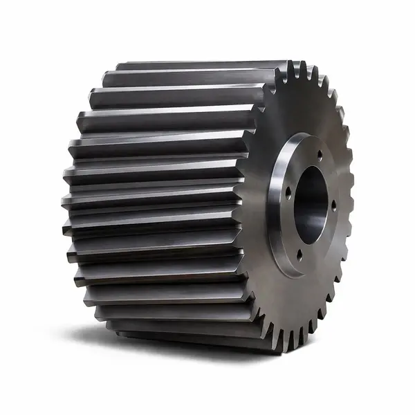
Carburized helical gear in service — four complementary monitoring methods detect different failure precursors at different rates of development. No single method is sufficient alone; effective service life management uses all four
Method 1: Oil Particle Count and Ferrographic Analysis
Oil sampling is the earliest indicator of helical gear tooth surface damage. As pitting initiates and progresses, wear particles enter the gear oil at increasing rates. ISO 4406 particle count monitoring tracks the particle count in three size ranges (≥4 µm, ≥6 µm, ≥14 µm) with each oil drain or on a scheduled interval. A rising particle count trend — particularly at sizes above 14 µm which indicate macro-pitting fragments — is the first measurable sign of gear tooth surface fatigue, typically detectable 200–1000 operating hours before the pitting is visible to the naked eye on inspection.
Ferrographic analysis (magnetic particle settling from an oil sample onto a glass slide, examined under microscope) identifies the particle shape, surface texture, and composition — distinguishing normal wear particles (thin laminar flakes, smooth surface) from fatigue spall particles (platelets with rough fracture surfaces, consistent with pitting) and cutting wear particles (curved worm-like particles indicating abrasive wear). A ferrographic report that shows increasing fatigue particle morphology confirms developing pitting in a helical gear drive.
Method 2: Vibration Signature Analysis
Vibration monitoring on the gearbox housing detects the periodic excitation from each tooth contact. A healthy helical gear pair produces vibration predominantly at the mesh frequency (f_mesh = z × RPM / 60) and its harmonics — with relatively low amplitude. As tooth surface damage develops (pitting, wear, root crack), additional vibration appears at the tooth period and its sidebands, and at sub-harmonic frequencies indicating the once-per-revolution modulation from a damaged tooth. A rise in vibration amplitude at mesh frequency or its sidebands typically indicates advancing pitting; a rise in low-frequency sub-harmonics combined with impact-type transient events can indicate root crack propagation.
Method 3: Backlash Measurement
Periodic backlash measurement on the assembled gearbox — by dial indicator on the gear rim at fixed intervals — tracks the progressive tooth flank wear that increases backlash over service life. For soft tooth flank industrial helical gears, a backlash increase rate above 0.025 mm per 1000 operating hours indicates accelerating wear, typically caused by inadequate lubrication or contamination. For hard tooth flank (carburized) gears, any measurable backlash increase above 0.05 mm over the first 5,000 hours is abnormal and should be investigated — carburized gears at correct operating conditions should show essentially no measurable backlash increase during their design life.
Method 4: Periodic Visual Inspection
Direct inspection of the tooth flanks — through the inspection cover or during a maintenance shutdown — is the definitive confirmation of pitting status. Initial pitting appears as small (0.1–0.3 mm) hemispherical craters at the pitch line; advancing pitting shows coalescence into larger spalled areas; end-stage pitting shows irregular crater fields with rough surfaces and metal fragments in the oil sump. The recommended visual inspection interval depends on the application’s consequence of failure: monthly for critical helical gears in mining and marine; quarterly for standard industrial gearboxes; annually for light-duty general industrial drives.
Replacement Decision Matrix — Run to Failure, Schedule at Next Shutdown, or Replace Immediately
| Observed Condition | Oil Particle Count Trend | Vibration Level | Decision |
|---|---|---|---|
| No visible pitting; normal wear marks only | Stable; ISO ≤16/14/11 | Stable; no sidebands | Continue operation; maintain monitoring schedule |
| Initial pitting (<3% flank area); small pits <0.5 mm at pitch line | Slowly rising; ISO 17/15/12 | Slight increase at mesh frequency | Plan replacement at next scheduled shutdown (typically 3–12 months); increase monitoring frequency |
| Active pitting (3–10% flank area); pits growing between inspections | Rising; ISO 18/16/13 or higher | Increasing; sidebands appearing | Schedule urgent replacement; order replacement helical gear immediately; run to next feasible shutdown only |
| Spalling (>10% flank area or single spall >5 mm) or any tooth fracture | High; large particles detected | High; impact transients present | Replace immediately — continued operation risks secondary damage to housing, shafts, and bearings from metal fragment ingestion |
Replacement Lead Time Planning — Why Early Ordering Matters
The most costly aspect of helical gear failures in industrial applications is not the gear itself but the unscheduled production downtime while waiting for a replacement. Korea Ever-Power’s standard lead time for a precision-ground industrial helical cut gear (M5–M16, OD 100–400 mm, carburized 20CrMnTi) is 4–8 weeks from confirmed drawing. For large mining or marine gears (M20–M50, OD 400–1200 mm), 14–24 weeks is typical. The decision matrix above shows that “Active pitting: order immediately” — if the condition monitoring programme gives 3–6 months of warning before the gear reaches the “replace immediately” threshold, the replacement can be ordered and ready before the forced shutdown.
Korea Ever-Power offers a planned replacement service: customers register their critical helical gears with their specification and planned replacement interval, and Korea Ever-Power holds the key design parameters on file — so that when the replacement order is placed, the drawing review and material selection are already completed, reducing the effective lead time by 1–2 weeks. As a direct helical gear manufacturer, Korea Ever-Power can also produce strategic spares from the original drawing when the gear is new — avoiding the longer reverse engineering lead time that arises when a worn gear is the only documentation source.

Frequently Asked Questions
Industry consensus (AGMA 1010-F14 and ISO 10825) defines acceptable pitting by the percentage of active tooth flank area affected and the severity of individual pits. As a practical guide: initial pitting of isolated pits under 0.3 mm diameter covering less than 3% of the active flank area is typically acceptable in soft tooth flank industrial gears and may arrest naturally during running-in. Active pitting — where the pitted area is growing between inspection intervals — is always unacceptable and requires replacement planning. For hard tooth flank (carburized) helical gears, any pitting above 1–2% of the flank area warrants accelerated monitoring and early replacement planning because carburized gears transition from initial pitting to spalling rapidly.
Only if the pitting depth is within the grinding allowance and the remaining case depth after grinding is still adequate for the contact stress requirements. For carburized helical gears with initial pitting (depth < 0.1 mm) and a ground surface Ra ≤ 0.4 µm already, there is typically 0.1–0.2 mm of material available for re-grinding before the case depth falls below the minimum specification. Korea Ever-Power accepts worn gears for re-grinding assessment — measuring the pitting depth and remaining case depth to confirm whether re-grinding is viable before committing to the operation. If re-grinding is not viable, reverse engineering and replacement is the correct path.
Contact fatigue life follows a steep power law: L_H ∝ (σ_H)^−6 per ISO 6336. This means life is proportional to (load)^−3 (since σ_H ∝ √load). A 10% increase in transmitted load increases σ_H by approximately 5%, and reduces life by (1.05)^6 − 1 ≈ 34%. A 20% overload reduces life by over 60%. This extreme load sensitivity is why service factor SF is so critical in helical gear specification — it is not a safety factor against fracture but a buffer against the cumulative fatigue life reduction from peak loads above the rated value. Even occasional overloads (monthly start-ups under load, surge loads from coupling misalignment) significantly reduce the total pitting life.
For registered customers with critical helical gears, Korea Ever-Power offers a consignment stock programme — one or two spare gears produced from the confirmed drawing are held at Korea Ever-Power’s warehouse, available for immediate dispatch in an emergency. The customer pays for the spare only when dispatched. Contact Korea Ever-Power’s team to discuss consignment stock terms for critical mining, marine, and process plant helical gear applications where unscheduled downtime cost justifies the holding stock investment.
Plan Your Helical Gear Replacement Before Unscheduled Failure
Register your critical helical gears with Korea Ever-Power. We hold the specification on file and confirm replacement lead time for planned and emergency orders — so a gear replacement decision translates to a shipped part in the shortest possible time.
Condition monitoring guidance · Lead time estimation · Strategic spare planning · Consignment stock programme
Editor: Cxm


























