
A rigorous mechanical evaluation of right-angle offset architectures versus parallel-axis transmission systems. Discover the critical differences in sliding friction, thermal efficiency, and high-torque load distribution.
Hypoid Gear vs Helical Gear — Executive Summary
When mechanical design engineers encounter spatial limitations within a power transmission system, selecting the correct geartrain architecture dictates the ultimate thermal behavior, acoustic signature, and mechanical longevity of the machine. At the absolute core of the hypoid gear vs helical gear engineering analysis is the fundamental geometric relationship between the driving input shaft and the driven output shaft.
A precision helical cut gear is predominantly designed to transmit rotational force between parallel shafts. By utilizing an inclined tooth profile—known as the helix angle—these gears initiate a gradual, diagonal rolling engagement that mitigates destructive mechanical shock and ensures continuous power delivery at exceptional efficiencies (frequently exceeding 98%). The fundamental kinematic action is primarily pure rolling friction across the pitch cylinder.
Conversely, a hypoid gear is a highly specialized variant of the spiral bevel gear family. It is uniquely engineered to transmit power between non-intersecting, perpendicular shafts. The defining characteristic is the mathematical “offset”—the pinion axis is physically lowered or raised relative to the centerline of the ring gear. While this architecture allows for larger pinion diameters and massive torque capacity in a 90-degree envelope, it introduces severe sliding friction across the tooth flanks, altering the entire tribological dynamic of the gearbox.

Geometric Foundations of Hypoid Gears

To fully comprehend the structural advantages of a hypoid transmission, one must isolate its unique mathematical geometry. A standard spiral bevel gear features axes that intersect perfectly at a single central point in space. A hypoid gear intentionally breaks this rule. The pinion shaft is offset, tracing the geometry of a hyperboloid of revolution rather than a simple pitch cone.
This architectural offset provides a profound mechanical advantage: it mathematically mandates an increase in the pinion’s spiral angle. Consequently, for any given gear reduction ratio, a hypoid pinion can be engineered significantly larger in physical diameter than a competing spiral bevel pinion. A larger pinion implies thicker, more robust tooth bases and an elevated contact ratio. With more teeth simultaneously engaged in the mesh, the hypoid architecture can transmit immense torsional shock loads within a highly compact right-angle footprint, making it the undeniable standard for heavy vehicle axles.
However, this geometry comes with a severe kinematic penalty. The non-intersecting layout forces the gear teeth to wipe and slide longitudinally across one another as they rotate. This violent sliding action generates massive thermal heat and fundamentally changes how the gearbox must be lubricated to survive continuous operation.
Kinematic Mechanics of Helical Cut Gears
Operating in stark contrast to the offset sliding nature of hypoid designs, a precision helical gear operates perfectly on parallel shafts. The fundamental defining characteristic is the helix angle—the specific degree to which the teeth are inclined relative to the rotational axis of the steel gear blank. This seemingly simple geometric shift entirely alters the physics of power transmission.
Progressive Involute Meshing
Because the teeth are set at a distinct angle, the initial contact between two mating helical gears does not occur across the entire face width simultaneously (as it does in a straight spur gear). Engagement begins as a microscopic point contact at one extreme edge of the leading tooth flank. As the shafts rotate, this contact point gradually and silently expands into a diagonal line, sweeping smoothly across the face until full engagement is achieved. This progressive kinematic action neutralizes violent impact shocks and deafening acoustic whine.
Pure Rolling Contact & Thrust
The definitive advantage of helical teeth is their pure rolling action at the pitch cylinder. By eliminating longitudinal sliding, mechanical efficiency remains incredibly high, resulting in substantially lower thermal energy generation. The primary engineering trade-off is the generation of axial thrust. The inclined helix angle produces a lateral vector force that attempts to push the gears apart horizontally, which must be managed by tapered roller bearings or negated entirely by utilizing a double helical gear (herringbone) design.

Tribological Differences: Sliding Friction vs Rolling Contact

Tribology—the precise science of friction, lubrication, and mechanical wear—is the definitive battleground in the hypoid gear vs helical gear selection process. Because of the mathematical offset, a hypoid pinion physically wipes across the mating gear. This severe longitudinal sliding friction acts somewhat like a worm gear, generating immense localized thermal energy that will instantly shear and vaporize standard hydrodynamic oil films. This causes boundary lubrication failure, leading to rapid metal-to-metal micro-welding and catastrophic scuffing.
To circumvent this inevitable destruction, hypoid systems are strictly dependent on specialized API GL-5 gear oils. These advanced lubricants are heavily fortified with high concentrations of sulfur-phosphorus Extreme Pressure (EP) additives. When localized temperatures spike due to sliding friction, these chemical additives actively react with the hot steel, continuously creating a sacrificial solid-lubricant film (iron sulfide) on the gear flank. This chemical layer shears off instead of the steel itself.
Parallel helical gears operate utilizing Elastohydrodynamic Lubrication (EHL). Because the primary motion is rolling rather than sliding, the synthetic gear oil is squeezed precisely into the mesh, temporarily undergoing a piezo-viscous phase change. The extreme pressure transforms the oil into an impenetrable solid wedge that physically separates the metal flanks. This allows helical gearboxes to run exceptionally cool, minimizing parasitic energy loss and maximizing fluid lifespan over decades of service.
Full Engineering Comparison Table
To aid mechanical engineers and procurement specialists in specifying the correct transmission architecture, the following matrix quantifies the exact physical, spatial, and thermodynamic metrics contrasting right-angle hypoid sets against parallel helical configurations.

| Engineering Metric | Helical Cut Gears | Hypoid Gears |
|---|---|---|
| Axis Spatial Orientation | Parallel shafts (Standard parallel power transfer). | Perpendicular (90°) right-angle with offset intersecting axis. |
| Fundamental Mesh Kinematics | Pure rolling motion at the pitch cylinder, virtually zero slip. | Heavy combination of rolling and continuous longitudinal sliding. |
| Tribological Efficiency | Exceptional: 98% – 99.5% per transmission stage. | Moderate: 90% – 95% (Lower efficiency due to sliding). |
| Thermal Energy Generation | Very low. Suitable for extreme high-speed continuous duty. | High. Sliding friction converts lost mechanical energy directly to heat. |
| Lubrication Requirements | Standard Industrial EP or Anti-Wear (AW) synthetic gear oils. | Mandatory API GL-5 fluids (high sulfur/phosphorus chemistry). |
| Bearing Load Vectors | Predictable radial loads and linear axial thrust based on angle. | Severe multi-directional thrust and separation forces. |
| Manufacturing Complexity | Standardized multi-axis CNC hobbing and form profile grinding. | Extremely high. Specialized face milling and abrasive lapping. |
Manufacturing and Metrology Complexities
The physical production of these components dictates their ultimate economic viability and scalability. Because the geometry of a hypoid tooth is based on a hyperboloid rather than a true involute curve, it cannot be generated on a standard hobbing machine. Hypoid gears require highly proprietary, immensely rigid face-milling or face-hobbing machinery (historically dominated by specialized Gleason or Klingelnberg systems). Furthermore, after the gears are thermochemically case-carburized to 60 HRC, correcting thermal warp is incredibly difficult. They are often “lapped” together in matched pairs using abrasive paste. Consequently, if a single hypoid pinion breaks in the field, the entire matched ring and pinion set must be completely replaced.

Helical components, owing to their strict involute geometry, are generated with extraordinary efficiency on ubiquitous vertical CNC hobbing machines. After the rigorous heat treatment process, the inevitable thermal distortion is rapidly and precisely corrected using multi-axis CNC continuous generation grinding or single-rib form grinding. Machines from premier builders like HÖFLER can achieve phenomenal DIN 3962 Class 3 to 6 tolerances. This guarantees that individual helical gears are entirely interchangeable, allowing for massive production scalability and streamlined maintenance protocols without the need for matched lapping.
Application Analysis: When to Specify Hypoid Gears
Hypoid gears represent a highly intentional engineering compromise. Designers willingly accept the inherent 5% to 8% energy loss and extreme lubrication requirements specifically to solve complex spatial architecture problems where massive torque must negotiate a 90-degree corner.
Automotive Rear-Wheel Drive Differentials
This remains the undisputed kingdom of the hypoid transmission. By dropping the pinion axis relative to the axle centerline, automotive designers can physically lower the entire longitudinal driveshaft beneath the vehicle chassis. This allows for a significantly lower, flatter cabin floor, reducing the central transmission tunnel intrusion. Furthermore, the massive pinion strength safely absorbs the violent kinetic shock of heavy vehicle acceleration from a dead stop.
Compact Right-Angle Robotics
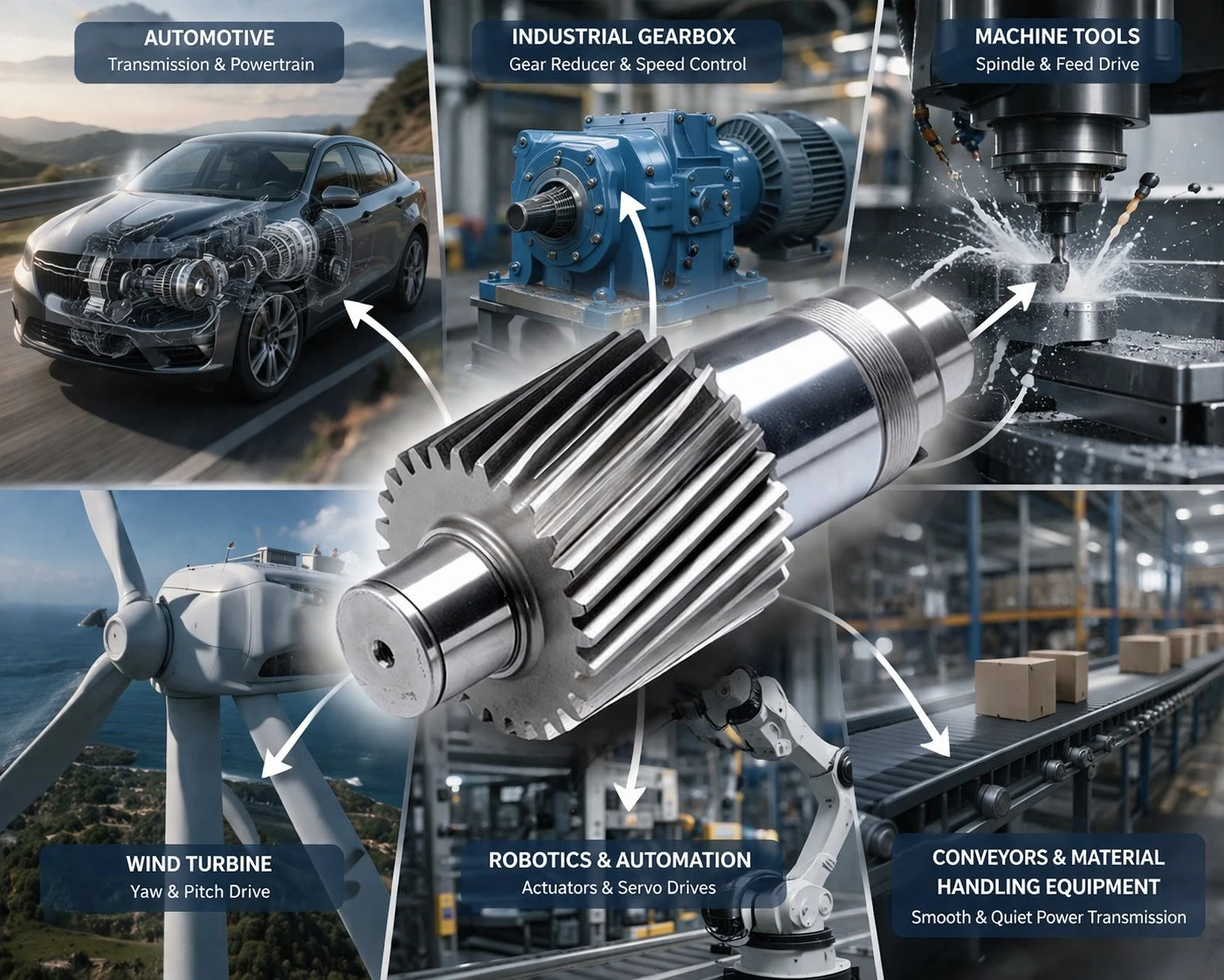
In multi-axis robotic arms, heavy industrial servos must deliver massive holding torque through tight, right-angle elbow joints. A standard spiral bevel gear would dictate that the bulky motor axis physically intersect the output axis. A hypoid offset permits the servo motor to completely bypass the center axis, resulting in an exceptionally compact, high-density robotic joint without sacrificing payload capacity.
Application Analysis: When to Specify Helical Gears
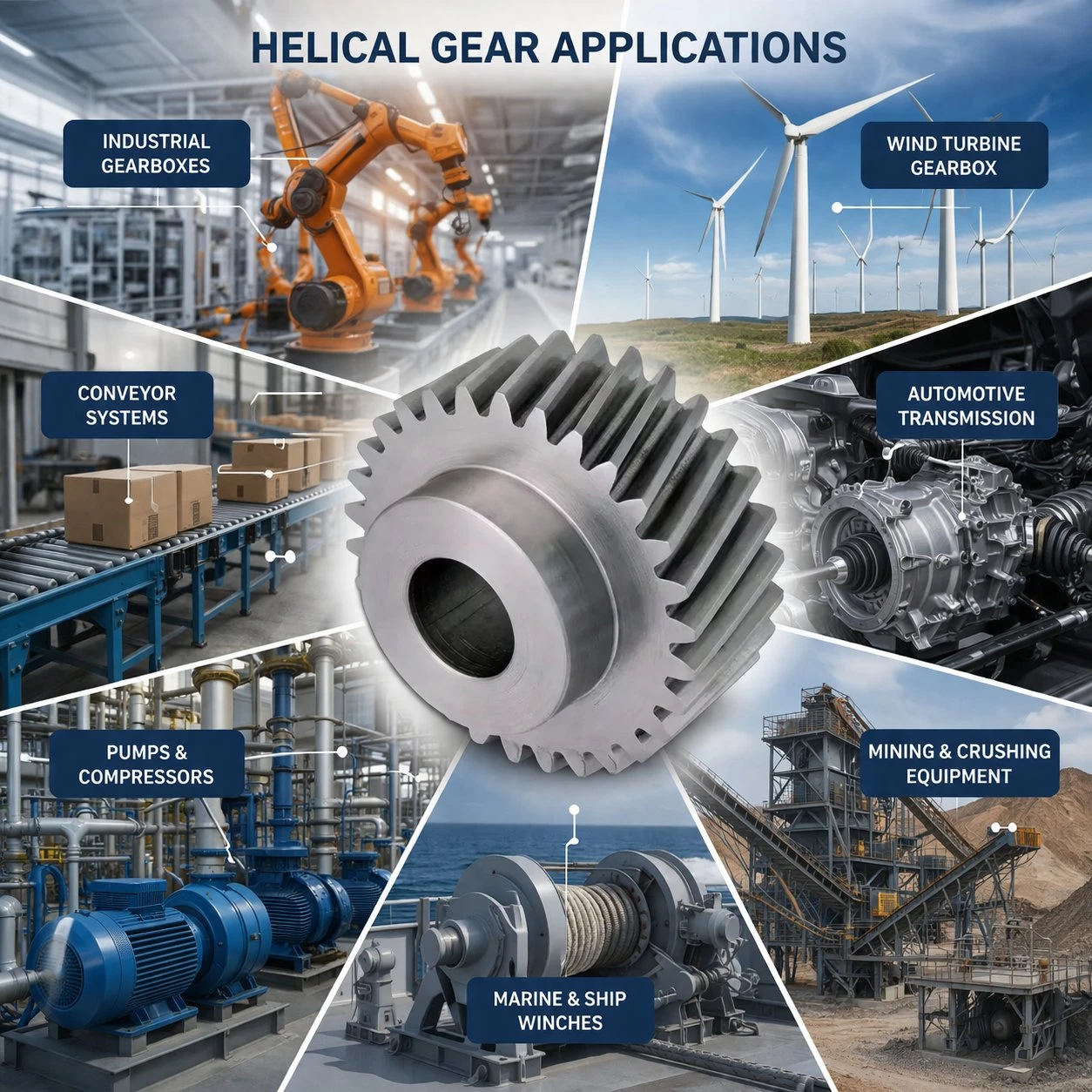
If the architectural constraints of the machine allow for parallel shafts, engineers will almost universally specify a parallel-axis helical transmission. The overwhelming driver for this decision is raw thermodynamic stability and absolute electrical efficiency.
Continuous-Duty Industrial Machinery
In sprawling industrial facilities, multi-megawatt electric motors drive heavy crushers, kilometer-long overland mining conveyors, and massive rotary gas compressors 24 hours a day. Losing nearly 10% of that massive electrical energy to the sliding friction heat of a right-angle drive is financially devastating and creates impossible cooling requirements. A multi-stage helical reducer maintains near-perfect 98.5%+ energy transfer continuously.
Electric Vehicle (EV) Powertrains
Precision ground helical gears are the undisputed standard for modern EV single-speed reduction drives. EV traction motors spin at astonishing velocities, frequently pushing past 20,000 RPM. At these extreme Mach speeds, the friction of a hypoid gear would instantly vaporize the oil film and destroy the gearbox. A DIN Class 4 ground helical gear runs silently, coolly, and flawlessly, prioritizing absolute battery range optimization.
Key Selection Factors — The Engineering Checklist
When finalizing the transmission blueprint, cross-reference these critical engineering constraints to isolate the optimal drivetrain geometry.
1. Spatial and Axis Constraints
If the power must navigate a tight 90-degree corner with intersecting clearance issues, specify hypoid. If the equipment envelope allows for a parallel motor and output shaft configuration, parallel helical is mandatory.
2. Thermodynamic Limits
Analyze the cooling capacity of the installation. High sliding friction inherently generates severe parasitic heat. If passive air cooling is insufficient and oil coolers cannot be installed, an efficient rolling helical mesh must be used.
3. Rotational Velocity (RPM)
Ultra-high-speed prime movers (turbines, EV motors) require precision ground involute helicoids. The boundary lubrication limits of offset right-angle drives make them unsuitable for continuous pitch-line velocities exceeding 30m/s.
Korea Ever-Power Precision Helical Gear Products
Architecting flawless power transmission systems requires unprecedented control over alloy metallurgy and sub-micron grinding metrology. Operating as an elite helical gear manufacturer headquartered in South Korea, Korea Ever-Power Worm Gear Co.,Ltd delivers unyielding mechanical reliability to the heavy industrial, marine, and automation sectors globally.

- ■ HÖFLER Topographical Modification: Utilizing premier German grinding technology, we engineer microscopic topological modifications—such as longitudinal lead crowning and involute tip relief—actively preventing destructive edge loading during severe industrial shaft deflection.
- ■ Immense Machining Scale: Our climate-controlled heavy infrastructure seamlessly processes massive forged alloy blanks with Outside Diameters (OD) reaching up to 2500mm, supplying replacement pinions for giant cement kilns and primary steel rolling mills.
- ■ Strict ISO 9001 Metallurgy: Every precision gear undergoes mandatory ultrasonic testing (UT) prior to machining and deep-case gas carburization, securing a 60 HRC wear-resistant outer shell supported by a virtually unbreakable ductile core.
Frequently Asked Questions
1. Can helical gears transmit power at a 90-degree right angle?
Yes, through a specific configuration known as a “crossed helical” drive, two helical gears can operate on perpendicular shafts. However, unlike the robust line-contact of a hypoid set, crossed helicals mesh at an infinitely small microscopic point. This extreme point-loading severely limits their torque capacity, restricting their use to very light-duty instrumentation or low-torque automated actuators.
2. What is the fundamental difference between a hypoid gear and a spiral bevel gear?
The definitive distinction is axis intersection. In a spiral bevel gear array, the center axis of the pinion intersects perfectly with the center axis of the ring gear on the exact same plane. A hypoid gear deliberately offsets the pinion shaft away from the ring gear’s centerline. This offset unlocks a larger pinion size for higher torque capacity but drastically increases sliding friction.
3. Why do hypoid gearboxes run significantly hotter than helical reducers?
The architectural offset of a hypoid gear forces the mating teeth to physically slide and wipe along the flank as they rotate under massive torque, generating intense frictional heat. A parallel shaft helical mesh relies on an incredibly efficient progressive rolling action. This distinct lack of sliding friction explains why helical gearboxes run significantly cooler and boast mechanical efficiencies nearing 99%.
4. What happens if I use standard industrial gear oil in a hypoid differential?
Using a standard GL-4 or basic anti-wear industrial oil in a hypoid gear set will result in rapid boundary layer failure. The extreme sliding pressure instantly shears the standard oil film, causing the bare steel surfaces to overheat and microscopically weld together. Hypoid sets strictly mandate API GL-5 oil, containing sulfur-phosphorus additives that create a chemical sacrificial layer to protect the metal from scuffing.
5. Which transmission architecture is quieter during high-velocity operation?
Both gear types are exceptionally quiet compared to straight spur gears due to their continuous, overlapping tooth engagement. Hypoid gears are often marginally quieter in high-torque automotive applications because the inherent sliding friction actively dampens high-frequency acoustic resonance. Conversely, high-speed helical gears achieve near-silent operation purely through micron-level HÖFLER profile grinding accuracy.
6. Are hypoid and helical gears manufactured on the same CNC equipment?
No. Precision parallel teeth are generated on standard vertical CNC hobbing machines and finished on continuous generating or form grinders. Hypoid gears demand highly specialized, dedicated Face-Milling or Face-Hobbing machinery utilizing circular cutter heads to carve the complex hyperboloid geometry into the conical gear blanks. They also frequently require paired lapping operations post-heat treatment.
Optimize Your Industrial Architecture
Thoroughly deciphering the engineering matrix of hypoid gear vs helical gear selection dictates the absolute thermal efficiency, acoustic footprint, and longevity of your machinery. Do not compromise massive capital equipment with substandard power transmission design. For continuous-duty parallel systems requiring DIN Class 3 accuracy and extreme torque capacity, Korea Ever-Power engineers provide the unyielding metallurgical foundation your operation demands.
Editor: Cxm


























