
A comprehensive mechanical engineering analysis of heavy-duty power transmission in metallurgical processing. Discover how precision-ground inclined tooth geometries, advanced topological micro-modifications, and massive herringbone pinion stands mitigate extreme impact shocks in heavy steel and aluminum rolling lines.
The Extreme Kinematics of Steel Mill Powertrains
Metallurgical rolling mills represent one of the most mechanically hostile and unforgiving ecosystems in the global heavy industry sector. The fundamental physical process of transforming a continuous-cast steel slab at 1200°C into a precision coiled sheet requires the continuous application of astronomical compressive separating forces. The prime movers generating this rotational energy are massive, multi-megawatt synchronous AC motors, but the critical architectural components responsible for safely translating that high-speed electrical energy into brutal, slow-speed crushing torque are the mechanical gearboxes. In this extreme operational theater, understanding the exact applications of helical gears becomes a profound exercise in structural dynamics, fatigue life management, and kinetic shock suppression.
The most critical mechanical event in any rolling operation is known as the “bite” or entry shock phase. This occurs at the exact fraction of a second when the leading edge of a thick, cold, or semi-hot steel billet violently impacts the narrow gap between the rotating upper and lower work rolls. This collision induces an instantaneous, explosive torque spike that propagates directly backward through the drive spindles and into the transmission gearing. If a mill drive were equipped with standard straight-cut spur gears, this instantaneous hammer-blow would concentrate millions of Newtons of kinetic force onto a single, isolated tooth interface across its entire face width simultaneously. This abrupt impact loading inevitably causes localized shear fracture, catastrophic root bending fatigue, and severe metallurgical spalling.
To survive decades of continuous 24/7 operation under these punishing physical parameters, heavy machinery engineers unilaterally specify helical gears in rolling mills. The diagonal tooth trace intrinsic to helical cut gears ensures that the catastrophic kinetic impact of the slab bite is progressively absorbed. By distributing the Hertzian contact stress over an elongated, overlapping line of action, these transmissions prevent immediate root failure while simultaneously suppressing the deafening acoustic resonance that would otherwise destroy the facility’s operational compliance.

Rolling Mill Application Matrix: Stand Constraints and Gear Specifications
A continuous hot strip mill or cold reversing mill is a cascading series of highly specialized mechanical zones. The kinetic demands placed on the drive trains vary drastically depending on whether the gearbox is installed at the initial roughing breakdown phase or the final high-speed tandem finishing phase. The matrix below benchmarks these extreme engineering parameters.

| Mill Stage / Component | Primary Operational Challenge | Specified Gear Architecture | Critical Engineering Focus |
|---|---|---|---|
| Roughing Stands (Breakdown) | Extreme impact shock loads during initial slab bite; massive low-speed torque amplification. | Double Helical / Single Helical; Huge Modules (m25+) | Root bending fatigue resistance; immense core ductility required to absorb kinetic shockwaves. |
| Pinion Stands (Torque Splitters) | 1:1 ratio continuous heavy torque transferring power to parallel twin rolls in confined space. | Continuous Herringbone; perfectly matched 50/50 pairs | Zero axial thrust operation is absolutely mandatory due to tight center-distance bearing constraints. |
| Finishing Mill Drives | High peripheral velocity; susceptibility to torsional resonance imprinting on the steel strip. | Precision Ground Single Helical; Lead Crowned | Minimizing transmission error to prevent “chatter marks”; strictly DIN Class 3/4 Accuracy. |
| Screw-Down Actuators (AGC) | Micro-adjusting roll gap distance against millions of pounds of upward separating pressure. | Right-Angle Worm Drive with Helical Primary Input | Absolute irreversibility (self-locking kinematics) to prevent rolls from springing open during the bite. |
Main Drive Reducers: Multi-Stage Torque Multiplication
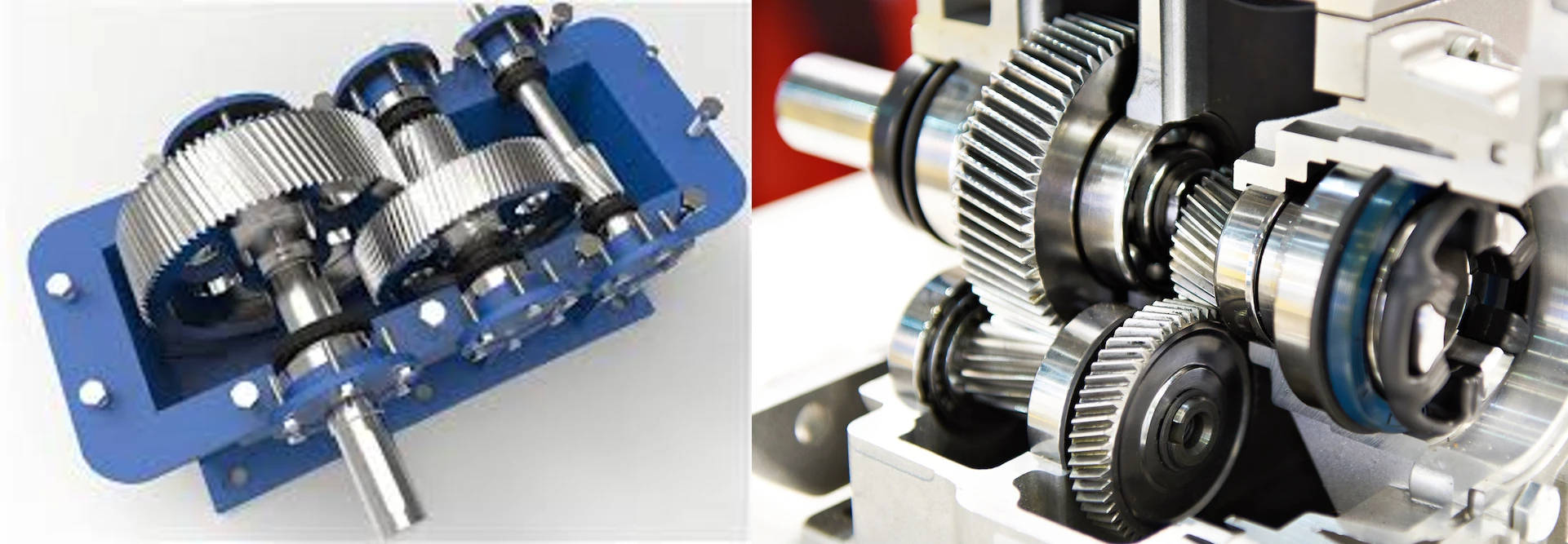
Before any torque can be applied to physically deform the steel strip, the high-speed rotation of the massive electric prime mover must be decelerated and transformed into raw twisting force. This conversion occurs within the Main Drive Reducer. These gearboxes are multi-stage behemoths, often weighing tens of tons, featuring heavily ribbed cast iron or fabricated steel casings. The high-speed input stages commonly utilize single helical gears precision-ground to extreme accuracy. The engineered overlap ratio of the angled teeth effortlessly absorbs the high-frequency input RPM without generating destructive acoustic whine.
Axial Thrust Containment Architecture
The primary mechanical consequence of utilizing single helical gears is the generation of severe lateral thrust vectors. As the gears rotate under heavy load, the inclined tooth angle actively pushes the gears sideways, attempting to blow out the housing. Because main drive reducers possess ample physical real estate within their massive casings, engineers can easily accommodate heavy-duty, multi-row tapered roller thrust bearings on the shaft journals. These heavy bearings safely absorb the lateral displacement vectors, preserving perfect shaft parallelism and allowing the gear train to operate at peak thermodynamic efficiency (often surpassing 98.5% per stage).
As the kinetic power translates down into the slow-speed output stages, the torque amplification becomes so immense that the resulting axial thrust vectors would physically shatter conventional thrust bearings. At this critical juncture, mechanical engineers often transition the drivetrain architecture to massive double helical gears, which safely swallow the extreme output torque while maintaining perfect axial equilibrium.
Pinion Stands: The Heart of Mill Synchronization
Positioned directly downstream from the main reducer lies the most geographically constrained and mechanically critical gearbox in the entire metallurgical facility: the Pinion Stand. A rolling mill functions by simultaneously compressing hot metal between an upper work roll and a lower work roll. These two massive rolls must be driven continuously in opposite directions, yet at the exact same rotational velocity.
The Center-Distance Engineering Dilemma
The pinion stand receives the single massive output shaft from the main drive and acts as a torque bifurcator, utilizing a 1:1 gear ratio to split that force equally into two outputs. The defining engineering nightmare of a pinion stand is its spatial constraint. The center distance between the two upper and lower pinions is geometrically dictated by the diameter of the work rolls they are driving. If the work rolls are 800mm in diameter, the gear center distance cannot exceed 800mm, otherwise, the drive spindles will converge and physically collide. Consequently, the pitch diameters of these gears are severely restricted, yet they must transfer 100% of the mill’s astronomical torque. To compensate for the limited diameter, metallurgical designers must utilize exceptionally long face widths, essentially turning the pinions into elongated, toothed cylinders.
Mandating the Herringbone Architecture
If standard single helical teeth were cut across these elongated face widths, the resulting lateral axial thrust would be so violently immense (often exceeding hundreds of kilo-Newtons) that no commercially available thrust bearing could safely contain it within the narrow housing block. To bypass this insurmountable physical constraint, the industry universally deploys the double helical gear geometry—often the continuous herringbone variant—for the pinion stand. By machining perfectly opposed left-hand and right-hand helical paths onto the identical long cylinder, the lateral thrust vectors push aggressively inward against each other and perfectly cancel out. This zero-thrust architecture permits the use of compact radial cylindrical roller bearings, allowing the massive gears to self-center dynamically under the violent shock of the billet bite.
Auxiliary Right-Angle Systems
While parallel helical drives dominate the main powertrain, auxiliary systems like coilers, cooling beds, and Automatic Gauge Control (AGC) screw-downs often require perpendicular power transfer. In these tight confines, engineers deploy worm gear actuators to provide immense mechanical advantage and absolute self-locking irreversibility against the massive separating forces of the mill.
Preventing Chatter Marks: Transmission Error in Finishing Trains
In the final finishing stands of a hot strip mill or a cold reversing mill, the steel is reduced to its final micrometer thickness at velocities frequently exceeding 20 meters per second. In this high-speed zone, raw torque absorption takes a backseat to absolute kinematic precision.

If the pinion stand or the main drive reducer contains microscopic pitch variations, poor involute form, or excessive mechanical backlash, the rotational velocity of the work rolls will rapidly micro-fluctuate. This phenomenon is known as transmission error. In a finishing mill, transmission error induces high-frequency torsional vibration that physically resonates down the drive spindles directly into the roll bite.
This vibration permanently embosses rhythmic thickness variations and visible transverse lines across the surface of the steel sheet. These highly destructive surface defects are universally rejected by automotive and aerospace buyers as “chatter marks.” To absolutely guarantee surface finish quality, the helical gears deployed in finishing drives are CNC ground to elite DIN ISO 1328 Class 3 or Class 4 tolerances. The combination of the diagonal overlapping mesh and sub-micron profile perfection ensures a buttery-smooth, constant velocity transfer, effectively insulating the work rolls from upstream mechanical vibration.
Metallurgical Integrity: Case Crushing and EHL Lubrication
Deep Case Carburization
Standard through-hardened carbon steel will shatter like glass under rolling mill shock loads. Mill pinions are forged from premium low-carbon, high-alloy steels (like 18CrNiMo7-6) and subjected to deep atmospheric carburizing. While standard gears require only 1.5mm of case depth, rolling mill gears frequently demand an Effective Case Depth (ECD) of 3.0mm to 5.0mm. This exceptionally thick arch of diamond-hard Martensite (60 HRC) prevents “case crushing”—a catastrophic failure mode where extreme compressive Hertzian forces cause a thin hardened shell to buckle into the softer core.
Elastohydrodynamic Lubrication (EHL)
The intense contact pressure generated inside a roughing mill reducer will instantly squeeze out standard mineral oil, causing immediate metal-to-metal friction welding and galling. Rolling mills must employ highly pressurized forced-lubrication systems using high-viscosity synthetic gear oils (ISO VG 320 to 680). These specialized lubricants are heavily fortified with Sulfur-Phosphorus Extreme Pressure (EP) additives that chemically bond to the steel surface under extreme heat, forming a sacrificial boundary layer that survives even when the hydrodynamic wedge breaks down during the entry shock.
Topological Crowning: Combating Mill Shaft Deflection
A rigid theoretical gear model plotted in CAD software assumes the supporting transmission shafts remain perfectly straight. In a heavy metallurgy environment, this assumption is dangerously false. When peak transient torque hits the incredibly wide face width of a pinion stand gear, the massive steel shafts physically bend, twist, and bow like a longbow.
If the inclined gear teeth were ground perfectly flat across the flank, this shaft deflection would instantaneously cause catastrophic “edge-loading.” The entire transmission force would shift away from the center of the gear and concentrate intensely onto the extreme outer corners of the teeth, fracturing them instantly.
As an elite South Korean helical gear manufacturer, Korea Ever-Power Worm Gear Co.,Ltd prevents edge-loading through advanced topological micro-modifications. Utilizing state-of-the-art German HÖFLER grinding centers, our technicians program deliberate “parabolic lead crowning” into the grinding cycle. By shaving microscopic microns of steel off the outer edges of the face width, we generate a highly engineered, barrel-shaped tooth profile. When the mill shaft inevitably bows under rolling torque, the crowned geometry acts as a dynamic pivot, ensuring the high-pressure contact patch remains safely centralized within the thickest, strongest core of the gear tooth.

Frequently Asked Engineering Questions
Why can’t straight spur gears be utilized in the roughing mill stage?
While technically possible in extremely antiquated, slow-speed mills, it is heavily discouraged in modern engineering. The initial impact of a cold slab entering the rolls generates a violent kinetic shockwave. The instantaneous full-face engagement of a straight spur gear transfers 100% of that shock directly into the root of a single tooth, frequently causing catastrophic shear failure. Angled teeth naturally distribute this shockwave across multiple parallel flanks simultaneously.
What is the functional difference between a Mill Reducer and a Pinion Stand?
A mill reducer is designed to multiply torque by dropping the high RPM of the electric motor down to the slow operating speed of the mill using staggered reduction ratios. A pinion stand does not reduce speed; it takes the single massive torque output from the reducer and splits it precisely 50/50 at a 1:1 ratio between two parallel shafts to drive the upper and lower work rolls simultaneously.
How is apex misalignment prevented in double helical pinion stands?
To ensure the massive torque is split perfectly evenly between the left-hand and right-hand tooth angles, one of the gears in a herringbone pinion stand must be allowed to “float” axially. By designing the shaft assembly without restricting thrust bearings on one gear, the mechanical forces naturally auto-center the apex, perfectly balancing the load and preventing unilateral spalling.
What is the typical Application Factor ($K_A$) used for rolling mill gear design?
Due to the violent nature of the billet bite and the potential for cold steel to jam in the rolls (cobbling), AGMA and ISO standards require exceptionally high Application Factors. A continuous hot strip finishing mill might require a $K_A$ of 1.5 to 1.75, while primary blooming and roughing mills—which suffer the most catastrophic shock loads—routinely demand a $K_A$ between 2.0 and 2.5, dictating incredibly massive gear modules.
How is backlash managed in an aging reversing mill pinion stand?
As rolling mill gears wear down over decades of use, the physical gap between the mating teeth (backlash) increases. During normal forward operation, this is manageable. However, in cold reversing mills, excessive backlash allows the motor to accelerate the pinion before it violently slams into the driven gear during directional changes. To mitigate this, worn pinion stands must either be refurbished via regrinding (and adjusting center distances via oversized bearings) or completely replaced with custom-cut, zero-backlash assemblies.
Secure Unstoppable Transmission Power for Your Mill
Catastrophic gearbox failure halts metallurgical production and decimates plant profitability. Do not entrust your heavy rolling mill drives to inferior manufacturing tolerances. Partner with Korea Ever-Power for massive, DIN-certified double helical and carburized drive components engineered specifically to dominate heavy industrial shock loads.
Editor: Cxm


























