
Two Independent Fatigue Limits — Why Both Must Be Checked
一个 螺旋齿轮 pair can fail through two entirely different mechanisms at the same operating load, and both must be checked independently because the material properties, geometry factors, and safety margins differ between them. Passing one check does not imply passing the other:
Check 1 — Pitting Resistance (Contact Fatigue)
The Hertz contact stress σ_H at the tooth flank must remain below the material’s allowable contact stress σ_H lim. Pitting is a surface fatigue mechanism — it initiates at or just below the tooth flank surface at the pitch line, where the EHL film is thinnest. It is progressive (warning before catastrophic failure) and governed by surface hardness. Typical minimum safety factor S_H min = 1.0–1.2.
Check 2 — Tooth Root Bending Strength
The bending stress σ_F at the tooth root fillet must remain below the material’s allowable bending stress σ_F lim. Tooth root fracture is a bending fatigue mechanism — it initiates at the tensile-side root fillet and propagates to catastrophic tooth fracture without warning. It is governed by core toughness and root geometry. Typical minimum safety factor S_F min = 1.3–2.0 (higher than pitting because failure is sudden).
The ISO 6336 Contact Stress Formula — Pitting Resistance Calculation
ISO 6336-2 calculates the nominal contact stress at the pitch point of a 螺旋齿轮 σ_H0 at the pitch point of a 螺旋齿轮 pair and then applies load influence factors to get the effective contact stress σ_H:
σ_H = Z_H × Z_E × Z_ε × Z_β × √( F_t/(b × d₁) × (u+1)/u ) × √(K_A × K_V × K_Hα × K_Hβ) [MPa]
| 因素 | 姓名 | Typical Value | Physical Meaning |
|---|---|---|---|
| Z_H | Zone factor | 2.35 at β=20°, α_n=20° | Converts tangential force to contact stress at the 螺旋齿轮 pitch point; reduces slightly with helix angle |
| Z_E | Elasticity factor | 189.8 √MPa (steel/steel) | Material elastic properties; fixed at 189.8 for any steel-on-steel gear pair |
| Z_ε | Contact ratio factor | 0.75–0.88 (lower = better) | Accounts for load sharing of the 螺旋齿轮 from total contact ratio; higher ε_γ reduces Z_ε, reducing σ_H — the helical gear advantage quantified |
| Z_β | Helix angle factor | √(cos β): 0.97 at β=20° | Accounts for the inclined contact line; modest benefit from helix angle beyond Z_ε |
| F_t/(b × d₁) | Unit load | N/mm² | Nominal Hertzian loading — the fundamental intensity before stress concentration |
| u | 齿轮比 | = z₂/z₁ | Curvature factor: higher u means the smaller gear (pinion) has higher contact stress than the larger gear |
| K_A | Application factor | 1.0–3.0 | External load variation (service factor); multiplies both contact and bending stress equally |
| K_Hβ | Face load distribution factor (contact) | 1.05–1.8 | Non-uniform load across 螺旋齿轮 face width; accounts for shaft deflection and misalignment. Reduced by lead crowning. |
The pitting safety factor for the 螺旋齿轮 pair (pinion and wheel checked separately):
S_H = σ_H lim_eff / σ_H ≥ S_H_min (typically 1.00 for general industrial; 1.20 for applications with uncertain load history)
The ISO 6336 Bending Stress Formula — Tooth Root Strength Calculation

Helical gear tooth cross-section — the tooth root fillet is the highest bending stress location in the entire gear. ISO 6336-3 calculates the nominal bending stress for a 螺旋齿轮 σ_F0 at this location and applies load influence factors K_A, K_V, K_Fα, and K_Fβ to obtain the effective stress for comparison against σ_F lim
σ_F = (F_t / (b × m_n)) × Y_Fa × Y_Sa × Y_ε × Y_β × K_A × K_V × K_Fα × K_Fβ [MPa]
| 因素 | 姓名 | Typical Value | Physical Meaning |
|---|---|---|---|
| Y_Fa | Tooth form factor | 2.5–3.5 (decreases with z) | Bending moment arm at the 螺旋齿轮 root fillet relative to tooth pitch; depends on tooth count and profile shift |
| Y_Sa | Stress correction factor | 1.55–1.80 | Stress concentration at root fillet; accounts for the notch effect of the fillet radius. Larger fillet → lower Y_Sa → lower σ_F |
| Y_ε | Contact ratio factor (bending) | 0.62–0.75 | Load sharing effect on bending; less reduction than Z_ε for contact because load still concentrates on individual teeth |
| Y_β | Helix angle factor (bending) | 1 − εβ × β/120 (approx.) | Helical contact line extends the root loading zone; moderate benefit for bending at β=20–25° |
| K_Fβ | Face load factor (bending) | 1.05–2.0 | Non-uniform load across face width; similar to K_Hβ but applied to bending. Edge loading from misalignment directly raises σ_F |
The bending safety factor for the 螺旋齿轮:
S_F = σ_F lim_eff / σ_F ≥ S_F_min (typically 1.40–1.60 general industrial; 2.00 for safety-critical applications)
Material Allowable Stresses — σ_H lim and σ_F lim Reference
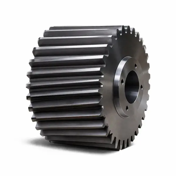
渗碳 螺旋齿轮 — the HRC 58–62 surface hardness achieved by gas carburizing delivers σ_H lim of 1500–1800 MPa (ISO 6336-5 MQ to ME material quality) — approximately 3× higher than a QT soft-flank gear, enabling either 3× the transmitted load or approximately 9× longer service life at the same load
| 材料等级 | 热处理 | 表面硬度 | σ_H lim (MPa) ISO MQ | σ_F lim (MPa) ISO MQ | ISO 6336-5 Quality |
|---|---|---|---|---|---|
| 45# (C45) | QT | HB 220–280 | 490–560 | 190–225 | ML (minimum) |
| 40Cr (41Cr4) | QT | HB 260–320 | 530–600 | 210–240 | ML |
| 42CrMo (42CrMo4) | Induction HRC 52 | HRC 50–55 | 820–950 | 340–380 | MQ |
| 20CrMnTi | Carburized + ground | HRC 58–62 | 1500–1650 | 430–480 | MQ to ME |
| 17CrNiMo6 | Carburized + ground | HRC 58–62 | 1600–1800 | 450–500 | ME (best) |
ISO 6336-5 material quality levels: ML = minimum; MQ = medium quality (industrial standard); ME = high quality (automotive and marine). σ_H lim and σ_F lim values from ISO 6336-5 Tables 1 and 2.
Worked Calculation Example — M5 Helical Gear Pair, 75 kW at 1500 RPM
Given: M5, z₁=24, z₂=72, β=20°, α_n=20°, b=80 mm, 20CrMnTi carburized, P=75 kW, n₁=1500 RPM, KA=1.25 (light shock)
Step 1 — Geometry
d₁ = 5 × 24 / cos20° = 127.8 mm | d₂ = 5 × 72 / cos20° = 383.4 mm
u = z₂/z₁ = 3.0 | C = (127.8 + 383.4)/2 = 255.6 mm
Step 2 — Tangential force and unit load
T₁ = 9550 × 75 / 1500 = 477.5 N·m
F_t = 2T₁ / d₁ = 2 × 477,500 / 127.8 = 7,475 N
F_t/b = 7,475 / 80 = 93.4 N/mm → Unit load w_t = F_t × (u+1)/(b × u) = 7475 × 4/(80 × 3) = 124.6 N/mm
Step 3 — Contact stress σ_H (simplified, KV=1.05, KHβ=1.15, KHα=1.0)
σ_H0 = Z_H × Z_E × Z_ε × Z_β × √(w_t)
= 2.35 × 189.8 × 0.79 × 0.970 × √(124.6)
= 2.35 × 189.8 × 0.79 × 0.970 × 11.16
= 380 MPa (nominal)
σ_H_eff = σ_H0 × √(KA × KV × KHβ × KHα)
= 380 × √(1.25 × 1.05 × 1.15 × 1.0)
= 380 × √1.509 = 380 × 1.229 = 467 MPa
Step 4 — Pitting safety factor
σ_H lim (20CrMnTi carburized, ISO MQ) = 1500 MPa
S_H = 1500 / 467 = 3.21 ✓ (minimum 1.0 — safely exceeded)
Step 5 — Bending stress σ_F (YFa=2.65, YSa=1.60, Yε=0.68, Yβ=0.88, KFβ=1.18)
σ_F0 = (F_t / (b × mn)) × YFa × YSa × Yε × Yβ
= (7475 / (80 × 5)) × 2.65 × 1.60 × 0.68 × 0.88
= 18.69 × 2.545 = 47.6 MPa
σ_F_eff = σ_F0 × KA × KV × KFα × KFβ
= 47.6 × 1.25 × 1.05 × 1.0 × 1.18
= 47.6 × 1.550 = 73.7 MPa
Step 6 — Bending safety factor
σ_F lim (20CrMnTi carburized, ISO MQ) = 450 MPa
S_F = 450 / 73.7 = 6.11 ✓ (minimum 1.4 — comfortably exceeded)
Which Limit Governs — Contact Fatigue or Bending Fatigue?

Korea Ever-Power performs ISO 6336 contact fatigue and bending fatigue calculations for every custom 螺旋齿轮 order — reporting S_H and S_F against the specified minimum safety factors and flagging any geometry change that would improve the strength margin
In practice, the governing limit — which of the two checks has the smaller safety factor margin — depends primarily on the gear size and material:
High transmitted power and speed (high F_t per unit face width); soft-flank QT material where σ_H lim is relatively low; large module gears where the tooth is tall and the root fillet is generous (low Y_Fa × Y_Sa). The 螺旋齿轮 pitch diameter must be increased or material upgraded to meet S_H_min.
Low tooth count pinion (z₁ < 18 → high Y_Fa); small module and narrow face width; reversing load (Y_M = 0.7); shock loading driving K_Fβ high; impact loads not fully captured in KA. The 螺旋齿轮 module must be increased or root fillet radius enlarged to meet S_F_min.
Korea Ever-Power — ISO 6336 Calculation with Every Industrial Order
Korea Ever-Power performs the full ISO 6336-2 and ISO 6336-3 strength calculation for every precision 螺旋齿轮 industrial order — reporting S_H and S_F for both pinion and gear wheel, with all K-factors explicitly stated. For customers providing power, speed, ratio, and application type, Korea Ever-Power’s engineering team selects the module and face width that achieves the target safety factors with the most cost-effective material. As a direct 螺旋齿轮制造商, Korea Ever-Power includes the ISO 6336 calculation summary in the order documentation, making the technical basis for the gear specification fully transparent. Browse the 螺旋齿轮产品系列 for industrial drive applications.
常见问题解答
The contact fatigue limit σ_H lim scales approximately with surface hardness squared (Hertz contact fatigue is a surface phenomenon governed by the hardened case). Tripling the surface hardness from HB 280 to HRC 60 more than triples σ_H lim. The bending fatigue limit σ_F lim scales more with core toughness than surface hardness — the tooth root fracture crack propagates through the core material, not the hard surface case. Increasing surface hardness improves σ_F lim only moderately (by improving the compressive residual stress in the root zone from the carburizing transformation) while dramatically improving σ_H lim. This asymmetry means that for carburized 螺旋齿轮, the pitting safety factor S_H is usually much higher than the bending safety factor S_F — bending fatigue more frequently governs the minimum acceptable gear size for carburized 螺旋齿轮 pairs.
The helix angle enters the ISO 6336 contact stress formula through three factors: Z_ε (contact ratio factor, improves with ε_β), Z_β (helix angle factor = √cos β, modest decrease with β), and Z_H (zone factor, slight decrease). The net effect of increasing β from 20° to 25° on σ_H is approximately −5 to −8% (i.e. lower contact stress, better pitting resistance) — primarily because ε_β increases from approximately 0.9 to 1.3 for a typical industrial gear, significantly reducing Z_ε. For the bending check, Y_β improves slightly with β, further reducing σ_F. Both safety factors improve when β is increased from 20° to 25°, at the cost of increased axial thrust (F_a increases by tan 25°/tan 20° = 1.28 × the original) — the usual tradeoff.
Yes — AGMA 2101 and ISO 6336 are based on the same fundamental Hertz contact stress and Lewis bending stress formulas, with different factor nomenclature and slightly different safety factor conventions. For most applications, a gear correctly rated to ISO 6336 with S_H ≥ 1.1 and S_F ≥ 1.5 will also pass AGMA 2101 rating criteria with appropriate service factor application. Korea Ever-Power performs ISO 6336 as the default calculation standard but can provide AGMA 2101 format output for customers who require it — the same 螺旋齿轮 is produced regardless of which standard the calculation is presented in.
ISO 6336 is intended to be conservative (pessimistic) for the median material quality (MQ level) — a gear that passes ISO 6336 at S_H = 1.0 should survive the design service life with good probability for average material and manufacturing quality. It can underestimate actual life for ME-quality material (premium carburized gears with very tight metallurgical control) and overestimate life when: material is at the lower bound of the MQ range; KA is underestimated (real peak loads exceed the assumed service factor); or misalignment factor K_Hβ is too low (residual misalignment after installation is higher than assumed in the calculation). For critical applications, Korea Ever-Power recommends specifying the actual K-factors from measured shaft deflection and housing alignment rather than using tabulated estimates.
Request ISO 6336 Strength Calculation for Your Helical Gear
Provide your power, speed, gear ratio, centre distance, and application type. Korea Ever-Power performs the full ISO 6336-2 (pitting) and ISO 6336-3 (bending) calculation and recommends the correct module, face width, and material to achieve the required safety factors — included as standard with every industrial gear order.
ISO 6336-2 pitting · ISO 6336-3 bending · S_H and S_F reported · All K-factors stated · Included with every order
编辑:Cxm


























