
The Short Answer — Why Axial Thrust Arises
A spur gear tooth is parallel to the shaft axis — the tooth contact force acts only in the plane of rotation (tangential and radial components, zero axial component). A helical gear tooth is inclined at angle β to the shaft axis. When the tooth transmits load, the contact force along the inclined tooth acts at angle β from the transverse plane — and the component of this force resolved along the shaft axis is the axial thrust. The larger the helix angle β, the greater the axial thrust relative to the transmitted tangential force.
The Physics — Force Resolution on a Helical Tooth
At the pitch point of a helical gear under transmitted torque T, three mutually perpendicular force components act on the tooth contact zone:
| Force Component | Symbol | Formula | Direction | Acts On |
|---|---|---|---|---|
| Tangential force | F_t | F_t = 2T / d = 2T cos β / (M_n × z) | Tangent to pitch circle, perpendicular to shaft axis | Transmits the torque — the “useful” component |
| Radial force | F_r | F_r = F_t × tan α_n / cos β | Radially outward from shaft centreline | Separates the two gears — loads radial bearings |
| Axial thrust | F_a | F_a = F_t × tan β | Parallel to shaft axis — the source of the problem | Loads thrust-capable bearings; must be absorbed by housing |
The axial thrust formula F_a = F_t × tan β is the key relationship. Notice that:
- At β = 0° (spur gear): tan 0° = 0, so F_a = 0. Spur gears have zero axial thrust. Every axial thrust issue with helical gears ultimately traces back to the non-zero helix angle.
- At β = 15°: F_a = F_t × tan 15° = 0.268 × F_t — axial thrust is 27% of tangential load
- At β = 25°: F_a = F_t × tan 25° = 0.466 × F_t — axial thrust is 47% of tangential load
- At β = 35°: F_a = F_t × tan 35° = 0.700 × F_t — axial thrust nearly equals transmitted force
Worked Numerical Example — Helical Gear Axial Thrust Calculation
Given: Helical Gear Drive Specification
Step 1: Pitch diameter of pinion
d₁ = M_n × z₁ / cos β = 5 × 24 / cos 25° = 120 / 0.906 = 132.4 mm
Step 2: Transmitted torque at pinion
T₁ = 9550 × P / n₁ = 9550 × 75 / 1500 = 477.5 N·m
Step 3: Tangential force
F_t = 2T₁ / d₁ = 2 × 477,500 / 132.4 = 7,213 N
Step 4: Axial thrust
F_a = F_t × tan β = 7,213 × tan 25° = 7,213 × 0.466 = 3,361 N
Step 5: Radial separating force
F_r = F_t × tan α_n / cos β = 7,213 × tan 20° / cos 25° = 7,213 × 0.364 / 0.906 = 2,898 N
Summary: The pinion bearing must support:
Tangential load F_t = 7,213 N (also loads radial bearings via shaft bending)
Axial thrust F_a = 3,361 N (requires angular-contact or taper-roller bearing at one end)
Direction of Axial Thrust — Right-Hand vs Left-Hand Helix
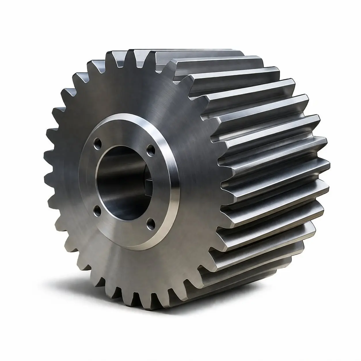
Axial thrust direction depends on helix hand and the gear’s role (driver vs driven). Single helical gears (left) generate unbalanced thrust; double helical herringbone (right) generates opposing thrusts that cancel internally to zero net axial force
The direction of axial thrust along the shaft (towards one end of the shaft or the other) depends on two factors: whether the gear is right-hand or left-hand helix, and whether the gear is the driver (receiving torque) or the driven (transmitting torque). The rules:
| Helix Hand | Gear Role | Rotation Direction (viewed from motor end) | Axial Thrust Direction |
|---|---|---|---|
| Right-hand (RH) | Driver (pinion) | Clockwise | Towards the left (away from motor) |
| Right-hand (RH) | Driver (pinion) | Counter-clockwise | Towards the right (towards motor) |
| Left-hand (LH) | Driver (pinion) | Clockwise | Towards the right (towards motor) |
| Left-hand (LH) | Driver (pinion) | Counter-clockwise | Towards the left (away from motor) |
How Helix Angle Affects Axial Thrust — Quantified
| Helix Angle β | tan β | F_a / F_t | Bearing Axial Capacity Required | Contact Ratio ε_γ Benefit |
|---|---|---|---|---|
| 0° (spur) | 0 | Zero | Deep-groove ball sufficient | No benefit |
| 8° | 0.140 | 14% | Standard angular-contact, light preload | Modest noise reduction |
| 15° | 0.268 | 27% | Angular-contact C15 or taper-roller | Significant noise and load benefit |
| 20° | 0.364 | 36% | Angular-contact rated for combined load | Standard automotive/CNC spec |
| 25° | 0.466 | 47% | Taper-roller or duplex angular-contact | Full contact ratio benefit |
| 30° | 0.577 | 58% | Heavy taper-roller or double helical config | Maximum single-helical benefit |
| 35° | 0.700 | 70% | Double helical strongly recommended | Marine / naval spec range |
The practical implication of this table is that the axial thrust rises faster than intuitively expected as helix angle increases. Between β = 15° and β = 25° — a common design range for industrial helical gears — the axial thrust nearly doubles (from 27% to 47% of F_t) while the noise benefit improvement is more modest. Designers who increase helix angle beyond 25° specifically for more noise reduction must verify that the thrust bearing at this angle remains within the standard angular-contact bearing’s capacity before specifying the change.
Three Engineering Solutions to Helical Gear Axial Thrust
Solution 1 — Angular-Contact or Taper-Roller Bearings
The simplest and most common solution. Angular-contact ball bearings (contact angle 15°, 25°, or 40°) carry both radial and axial loads simultaneously. For the helical gear shaft, one end of the shaft has a pair of back-to-back angular-contact bearings that react the axial thrust in one direction; the other end has a deep-groove (radial only) bearing that accommodates the shaft’s thermal expansion. This is the standard bearing arrangement for the majority of helical gear drives at β = 15–25°. Cost impact: angular-contact bearings cost approximately 1.5–2.5× equivalent deep-groove ball bearings in the same bore size — a modest premium fully justified by the helix angle’s noise and load capacity benefits.
Solution 2 — Opposing Helix Hand in Tandem Multi-Stage Drives
In a 2-stage or 3-stage helical gear gearbox, specifying right-hand helix on the first stage and left-hand on the second stage produces equal and opposite axial thrusts on the intermediate shaft — which carries the first-stage driven gear and the second-stage driver gear on the same shaft. If the stage ratios are similar, the axial thrusts partially cancel, and the intermediate shaft bearing needs to absorb only the difference. This “tandem stage thrust cancellation” is a cost-effective design technique that avoids the need for heavy-duty thrust bearings on the intermediate shaft while maintaining the full noise and contact ratio benefits of helical gearing on both stages.
Solution 3 — Double Helical (Herringbone) Configuration
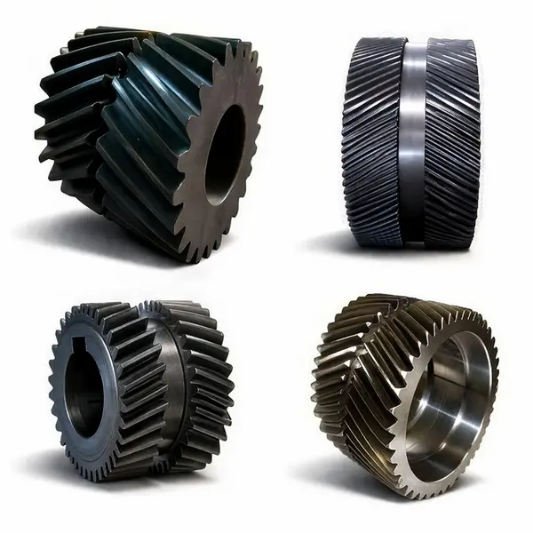
The double helical herringbone gear — the complete engineering solution to helical gear axial thrust. Opposing helix sections generate equal and opposite F_a forces that cancel at the gear body, leaving zero net axial force on the shaft for any helix angle
A double helical (herringbone) gear has two helix sections — one right-hand and one left-hand — of equal face width on the same gear body. The axial thrust from the right-hand section is exactly cancelled by the equal and opposite axial thrust from the left-hand section. The net axial force on the shaft is zero, regardless of the helix angle. This allows very large helix angles (β = 30–45°) for maximum contact ratio and minimum noise without any axial thrust at the shaft. The trade-off is manufacturing complexity: the central relief groove, matched pair hobbing, and grinding access constraints add 25–60% to the gear unit cost compared with a single helical gear of equivalent capacity. See double helical gear for detailed herringbone design engineering data.
When Does Axial Thrust Cause Practical Problems?
Most helical gear drives handle axial thrust without incident throughout their design life. The cases where axial thrust creates operational problems are:
The most common root cause of premature thrust bearing failure in helical gear drives. The designer specifies angular-contact bearings sized for the radial gear force only, overlooking F_a = F_t × tan β. At β = 25°, this means the thrust bearing is underrated by the factor tan 25° = 0.47 — nearly half the actual combined load is unaccounted for. In multi-stage gearboxes where each shaft has both a driven and a driving helical gear, the shaft’s net axial load is the vector sum of both gear thrusts — which may add or partially cancel depending on helix hand selection.
Ball mill trunnion bearings, ship propeller shaft stern tube bearings, centrifuge spindle bearings, and thread-rolling machine crosshead bearings are designed as radial bearings with zero or very limited axial load capacity. If a single helical gear drives these mechanisms, its axial thrust loads the downstream bearing in an unintended direction. The correct solution is always to use a double helical gear or to interpose a thrust bearing between the gear shaft and the sensitive mechanism.
In crane hoists and reversing drives, the helical gear must transmit torque in both directions. When the rotation reverses, the axial thrust direction reverses — the bearing that was in compression becomes the tension bearing. The bearing arrangement must accommodate bidirectional axial load; a single back-to-back pair of angular-contact bearings handles this correctly; a tandem pair (both pointing the same way) does not.
Korea Ever-Power — Bearing Arrangement Consultation for Helical Gear Applications

A precision HÖFLER-ground helical gear — the axial thrust from its helix angle must be absorbed by a correctly rated bearing arrangement that is sized at the quotation stage, not discovered after the gearbox is assembled and installed
Korea Ever-Power’s engineering team reviews bearing arrangement requirements as part of every helical cut gear order — confirming the correct F_a value, thrust direction, and bearing type recommendation so that the customer’s gearbox designer has the information needed before housing and bearing are specified. As a direct helical gear manufacturer, Korea Ever-Power supplies not just the helical gear itself but the complete force data package — F_t, F_r, F_a, with direction vectors — that the gearbox housing and bearing engineer needs to complete the design.
Frequently Asked Questions
A spur gear tooth is parallel to the shaft axis (helix angle β = 0°). The contact force at any point on the spur tooth lies entirely in the transverse plane — there is no component of force in the axial direction, so no axial thrust is generated. A helical gear tooth is inclined at β, and the contact force at the inclined tooth surface has a component resolved along the shaft axis: F_a = F_t × tan β. This is the fundamental geometric reason: the inclined tooth converts some of the transmitted tangential force into an axial component, while simultaneously spreading the contact over a longer diagonal contact line — which gives all the noise and load capacity benefits of the helical form.
Not directly. The axial thrust formula F_a = F_t × tan β depends on the tangential force F_t (determined by transmitted torque T and pitch diameter d) and the helix angle β. The gear ratio i = z₂/z₁ affects how the torque divides between pinion and gear: the gear torque is T₂ = T₁ × i, and the gear pitch diameter is d₂ = d₁ × i, so the gear’s tangential force F_t₂ = 2T₂/d₂ = 2T₁i/(d₁i) = F_t₁ — the tangential forces on pinion and gear are equal and opposite (Newton’s third law). Therefore the axial thrust on the pinion shaft and the gear shaft are equal in magnitude but opposite in direction, regardless of the gear ratio.
Yes, by reducing the helix angle β. F_a = F_t × tan β means a smaller β directly reduces F_a. However, reducing β also reduces the noise and load capacity benefits of the helical gear form — the advantage is proportional to helix angle. The minimum practical helix angle for meaningful noise reduction over a spur gear is approximately β = 8–10°. The typical industrial compromise — β = 15–25° — was developed precisely to balance the noise and contact ratio benefits against the axial thrust penalty. Below β = 15°, the thrust is modest but so are the benefits. Above β = 25°, the benefits are maximised but thrust bearing requirements become significant.
For helical gear drives at β = 15–25°, the standard solution is paired angular-contact ball bearings in back-to-back (DB) arrangement, or a single taper-roller bearing. For β = 25–35°, heavy-duty taper-roller bearings or duplex angular-contact bearings. The bearing must be sized for the combined radial and axial load using the bearing manufacturer’s dynamic equivalent load calculation: P = X × F_r + Y × F_a (where X and Y are the radial and axial load factors for the selected bearing type and contact angle). The bearing must also be specified as the “located” bearing — the other bearing on the shaft is the “floating” bearing that can move axially to accommodate thermal expansion and avoid over-constraint.
Premature bearing failure — typically within months to a year of initial operation, rather than the designed 50,000–100,000 hour L10 life. The failure mode depends on what bearing was specified: a deep-groove ball bearing with no axial capacity fails quickly by cage fracture and ball skidding from the unexpected axial loading; an undersized angular-contact bearing fails by overloaded raceway pitting and eventual spalling. In both cases, the failure appears as “bearing failure” and is frequently misdiagnosed as a lubrication or installation problem rather than the original cause: incorrect bearing selection for the helical gear’s axial thrust at the specified helix angle.
Need Axial Thrust Calculation for Your Helical Gear Drive?
Korea Ever-Power provides complete force data — F_t, F_r, F_a with direction vectors — for every helical gear order, giving your bearing and housing engineers the inputs needed to correctly specify the thrust bearing arrangement. Submit your power, speed, and helix angle requirements.
F_t · F_r · F_a · direction vectors · bearing recommendations · standard with every order · MOQ 1 piece
Editor: Cxm


























